
Published
Evaluating drag force and geometric optimisation of pipeline inspection gadget (PIG) body with bypass
Evaluación de la fuerza de arrastre y optimización geométrica del cuerpo de un PIG con baipás
DOI:
https://doi.org/10.15446/ing.investig.v31n2.23474Keywords:
CFD, fluid structure interaction, optimisation, PIG, pipeline. (en)CFD interacción fluido-estructura, optimización, PIG, oleoductos. (es)
Downloads
A pipeline inspection gadget (PIG) is a device used to run through pipelines for cleaning, measurement and inspection operations. By-pass is the name for one or a set of orifices allowing flow from back to front of a PIG. It is used for speed control or to improve cleaning operations results. By-pass prevents speed excursions in gas pipelines thereby avoiding damage to the PIG or the pipe. Studies and algorithms have been developed to simulate the dynamics of PIGs running inside pipes. Most studies have been for gas pipelines; these have helped to design some PIG models. This work summarises a particular stage during a PIG design project. This PIG will work in liquid pipelines and can stop in the line for inspection and maintenance tasks. Studying fluid force on a PIG when it has low or zero speed is needed for evaluating project feasibility and conceptual design. Selecting a PIG form to minimise the force of interaction with fluid allows a low weight design and lower energy loss.
Un PIG es un dispositivo o vehículo que se desplaza entre ductos, siendo utilizado en operaciones de limpieza, medición e inspección, principalmente aplicado en oleoductos y gasoductos. Baipás es el nombre de uno o varios orificios que permiten el paso de fluido de atrás hacia adelante del PIG. Es utilizado para controlar la velocidad o para mejorar el resultado de las operaciones de limpieza. En gasoductos el baipás controla las variaciones bruscas de velocidad, evitando daños en el PIG o el ducto. Estudios y algoritmos han sido desarrollados para simular la dinámica de los PIG y su paso por los ductos. La mayoría de estos estudios son sobre ductos con gas y han servido para el diseño de algunos modelos de PIG. Este trabajo describe parte del diseño de un PIG que trabaja con líquidos, capaz de realizar tareas de inspección o mantenimiento dentro del ducto. El estudio de la fuerza que ejerce el fluido en el PIG cuando tiene baja o nula velocidad es necesario para evaluar la viabilidad del proyecto y la concepción del diseño. Al mismo tiempo, definir una forma geométrica del PIG que minimice la fuerza de interacción con el fluido permite diseñar un PIG más liviano y que cause menores pérdidas de energía.
Evaluación de la fuerza de arrastre y optimización geométrica del cuerpo de un PIG con baipás
Evaluating drag force and geometric optimisation of pipeline inspection gadget (PIG) body with bypass
Ricardo Ramírez1, Max Dutra21 Ingeniero Mecánico, Departamento de ingeniería Mécanica y Mecatrónica, Universidad Nacional de Colombia, Colombia. reramirezh@unal.edu.co
2 Programa de Ingeniería Mecánica, COPPE, Universidad Federal de Río de Janeiro, Brasil. max@mecanica.coppe.ufrj.br
RESUMEN
Un PIG es un dispositivo o vehículo que se desplaza entre ductos, siendo utilizado en operaciones de limpieza, medición e inspección, principalmente aplicado en oleoductos y gasoductos. Baipás es el nombre de uno o varios orificios que permiten el paso de fluido de atrás hacia adelante del PIG. Es utilizado para controlar la velocidad o para mejorar el resultado de las operaciones de limpieza. En gasoductos el baipás controla las variaciones bruscas de velocidad, evitando daños en el PIG o el ducto. Estudios y algoritmos han sido desarrollados para simular la dinámica de los PIG y su paso por los ductos. La mayoría de estos estudios son sobre ductos con gas y han servido para el diseño de algunos modelos de PIG. Este trabajo describe parte del diseño de un PIG que trabaja con líquidos, capaz de realizar tareas de inspección o mantenimiento dentro del ducto. El estudio de la fuerza que ejerce el fluido en el PIG cuando tiene baja o nula velocidad es necesario para evaluar la viabilidad del proyecto y la concepción del diseño. Al mismo tiempo, definir una forma geométrica del PIG que minimice la fuerza de interacción con el fluido permite diseñar un PIG más liviano y que cause menores pérdidas de energía.
Palabras clave: CFD interacción fluido-estructura, optimización, PIG, oleoductos.
ABSTRACT
A pipeline inspection gadget (PIG) is a device used to run through pipelines for cleaning, measurement and inspection operations. By-pass is the name for one or a set of orifices allowing flow from back to front of a PIG. It is used for speed control or to improve cleaning operations results. By-pass prevents speed excursions in gas pipelines thereby avoiding damage to the PIG or the pipe. Studies and algorithms have been developed to simulate the dynamics of PIGs running inside pipes. Most studies have been for gas pipelines; these have helped to design some PIG models. This work summarises a particular stage during a PIG design project. This PIG will work in liquid pipelines and can stop in the line for inspection and maintenance tasks. Studying fluid force on a PIG when it has low or zero speed is needed for evaluating project feasibility and conceptual design. Selecting a PIG form to minimise the force of interaction with fluid allows a low weight design and lower energy loss.
Keywords: CFD, fluid structure interaction, optimisation, PIG, pipeline.
Introducción
Los PIG son dispositivos, herramientas o vehículos autocontenidos e independientes, que se mueven entre ductos y se utilizan en operaciones de limpieza, dimensionamiento e inspección (PPSA, 2010) tradicionalmente aplicadas en oleoductos y gasoductos. La velocidad de desplazamiento de los PIG varía debido a las irregularidades del tubo, a los cambios en las condiciones físicas entre las superficies en contacto y a variaciones en el caudal. Los cambios de velocidad son mayores en gasoductos por la compresibilidad del fluido, y llegan a ser peligrosos para la integridad del PIG o del tubo. El fenómeno de grandes aceleraciones es conocido como excursiones de velocidad (Mattheus et al, 2007). El uso de ori ficios llamados baipás en el cuerpo del PIG es una de las formas de atenuar las excursiones de velocidad.
Un baipás permite el paso de fluido de atrás hacia adelante del PIG y tiene como resultado que la velocidad de desplazamiento del dispositivo sea diferente de la velocidad media de flujo. Se han realizado varios estudios para diseño de PIG con baipás (Nguyen et al, 2001; Boe, 2007; Korea Gas Corporation, 2010; Podgorbunskikh, 2008). En algunos casos los orificios de baipás son utilizados para obtener chorros del mismo fluido a los fines de mejorar los resultados de las pasadas de limpieza. En otros casos se adiciona al orificio una válvula que permite controlar la velocidad del PIG (Frota, 2007).
Se proyecta un PIG para oleoductos que tenga como características especiales la capacidad de control de velocidad y la de parar dentro del ducto mientras éste continúa transportando combustible.
El concepto inicial para el cuerpo del PIG es un cilindro con un orificio central que actúe como baipás. El cuerpo va soportado por discos de poliuretano similares a los que se usan en los actuales PIG de limpieza. En el orificio será colocada una válvula que lleva a cabo el control de velocidad, de parada y de arranque. El diseño de está válvula no está incluido en el alcance del presente trabajo.
El objetivo es el de optimizar la forma y las dimensiones del ilindro para lograr dos propósitos: minimizar la fuerza de interacción entre el fluido y el cuerpo, y maximizar el volumen del cuerpo. El primero de ellos permite disminuir los requerimientos de diseño mecánico y de control de la válvula, además de la pérdida de energía causada por la presencia del PIG en el ducto. El segundo permite un mayor volumen interno disponible dentro del cuerpo para colocar elementos como baterías, placas electrónicas y actuadores.
Procedimiento
La optimización de forma es realizada en dos etapas. En la primera se considera el orificio de baipás con diámetro constante y se obtiene el diámetro óptimo. En la segunda el orificio es modificado a formas que correspondan a varios perfiles propuestos con el fin de reducir más la fuerza de interacción. Se seleccionan el mejor perfil y las dimensiones óptimas para ese perfil.
Durante el proceso de optimización para las dos etapas se encontró que al mudar las dimensiones del cuerpo del PIG, si disminuye la fuerza de interacción también se reduce el volumen del cuerpo. Eso significa que si un objetivo se acerca a su valor óptimo el otro objetivo se aleja; se tiene un caso de objetivos en conflicto, y la obtención del valor óptimo de diámetro se hizo utilizando el concepto de frontera de Pareto (Araújo et al, 2009).
Materiales y métodos
Especificaciones generales
El modelo estudiado está formado por un segmento de tubo y el PIG (figura 1 ). El tubo es cilíndrico, recto y horizontal. El diámetro nominal escogido en el proyecto es de 12 pulgadas, que corresponde a un tubo de diámetro interno de 304,8 mm y externo de 323,85 mm; la longitud es de 4 m y la rugosidad interna de 25 micrómetros típica para ductos de acero nuevos (Stukenbruck, 2008).
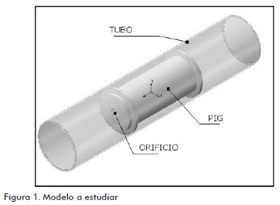
El modelo usado para simular el PIG es un cilindro con salientes que simulan los discos de raspado, tiene un orificio axial cuya forma y dimensiones varían para los diferentes casos a ser simulados. El diámetro externo corresponde con el diámetro interno del tubo. La longitud de PIG usada es dos veces el diámetro interno del tubo, una relación comúnmente utilizada por los fabricantes de PIG la cual permite que el PIG no quede atascado en las curvas del ducto.
El fluido considerado es gasolina con densidad constante de r = 747 kg/m3 y viscosidad dinámica μ = 6,57 x 10⁻⁴ Pa·s, también constante. La velocidad del flujo máxima es de 5 m/s, que corresponde a la velocidad utilizada típicamente en poliductos que transportan productos refinados.
Cálculo del diámetro de orificio óptimo
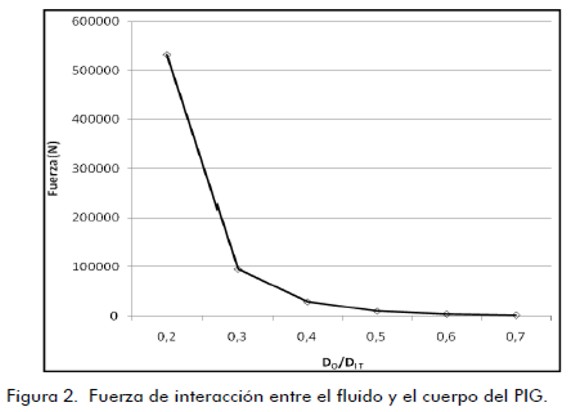
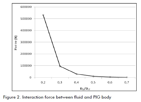
El diámetro del orificio (DO) se varía de 10% a 70 % del diámetro interno del tubo (DIT) en pasos de 10%. La fuerza (F) que ejerce el fluido sobre el cuerpo del PIG en la dirección de desplazamiento se evalúa para cada caso utilizando una herramienta de dinámica computacional de fluidos (CFD). El resultado de la fuerza como función de la relación DO/DIT es presentado en la figura 2 .
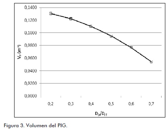
Para cada caso es calculado también el volumen del cuerpo del PIG (VP) (ecuación 1 ).
 | [1] |
donde DE es el diámetro externo del PIG y LP la longitud del cuerpo del PIG. El resultado es presentado en la figura 3.
Al aumentar el diámetro del orificio la fuerza disminuye y el volumen aumenta. Como se desea minimizar la fuerza y maximizar el volumen, se concluye que los dos objetivos están en conflicto. Por otro lado, los órdenes de magnitud de la fuerza y del volumen no son comparables. Para obtener el diámetro óptimo se definen dos funciones, f1 y f2 (ecuaciones 2 y 3):
 | [2] |
 | [3] |
La función f1 normaliza la fuerza a un rango entre 0 y 1, y para minimizar la fuerza se debe minimizar f1. La función f2 normaliza el volumen a un rango entre 0 y 1 para hacerlo comparable con la función f1 y para maximizar el volumen se debe minimizar f1.
Se define una nueva función (ecuación 4):
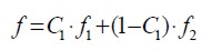 | [4] |
El parámetro C1 es un criterio de diseño mediante el cual el diseñador puede dar mayor o menor importancia al objetivo de minimizar la fuerza o de maximizar el volumen. C1 se hace variar de 0 a 1 en pasos de 0.1. Si C1 es pequeño significa que para el diseño es más importante maximizar el volumen que minimizar la fuerza, y si C1 es grande significa la condición contraria.
Para cada valor de C1 el diámetro óptimo es el que minimiza la función f. Los resultados representan la frontera de Pareto (figura 4).
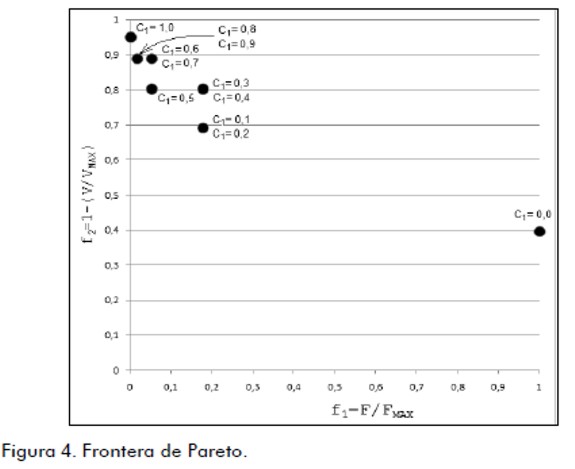
Se seleccionó un criterio que equilibre los dos objetivos, el cual corresponde al valor C1 = 0,5. El diámetro óptimo que minimiza la función f es de 0,06 m o 60 mm.
Selección y optimización del perfil del orificio
El uso de un cuerpo con un baipás de diámetro constante hace que el flujo tenga dos cambios bruscos de área, una contracción súbita en la parte trasera del PIG y una expansión súbita en la parte delantera que generan pérdidas de carga y que pueden ser reducidas al modificar el perfil del orificio para que la contracción y la expansión sean más suaves.

Resultados
La fuerza en todos los casos fue calculada utilizando el software de CFD. El volumen fue calculado mediante una fórmula geométrica en el primer perfil y por integración del sólido de revolución para el segundo y el tercer perfil.
Resultados para el perfil tipo cónico
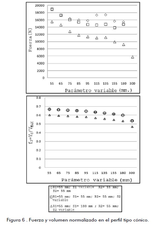
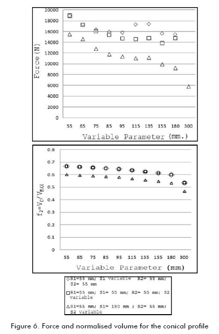
Los resultados de fuerza y de la función de volumen normalizado del cuerpo para el perfil tipo cónico son presentados en la figura 6.
Resultados para el perfil tipo bocal
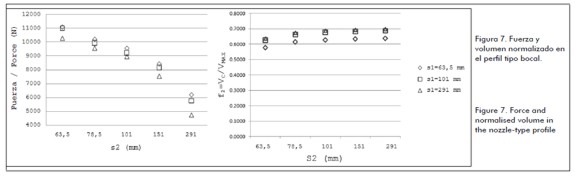
Los resultados de fuerza y de la función de volumen normalizado para el perfil tipo bocal son presentados en la figura 7.

Resultados para el perfil tipo polinómico
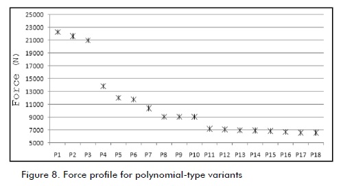
Los resultados de fuerza para el perfil tipo polinómico son presentados en la figura 8. El número de perfiles posibles es mayor por la dependencia de seis parámetros. A los objetos de obtener los perfiles con la menor fuerza fue llevado a cabo un proceso tipo algoritmo genético. Se generaron de forma aleatoria conjuntos de valores r2, s1 e i2 (figura 5(c)) y con cada conjunto fue calculado y construido el correspondiente perfil. El cálculo de fuerza fue hecho para este conjunto de perfiles. Los perfiles correspondientes a los casos con fuerza menor, fueron seleccionados y los parámetros de estos perfiles se cruzaron para generar una segunda generación de perfiles. Nuevamente se hicieron corridas de software para calcular las fuerzas.

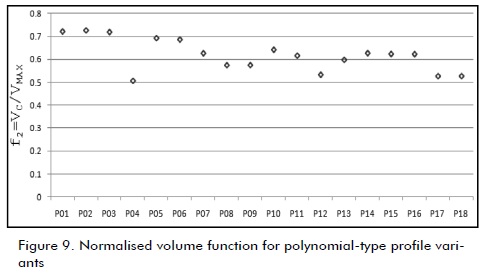
Los resultados de la función de volumen normalizado son presentados en la figura 9. Los perfiles sobre los que son calculados los resultados se nombran consecutivamente como P1 hasta P18.

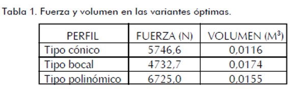
Para cada uno de los perfiles fue aplicado un proceso de optimización multiobjetivo similar al descrito para la obtención del diámetro de orificio óptimo. Así, en cada conjunto de variantes fue seleccionada una como la variante óptima de cada tipo de perfil que minimiza la fuerza y maximiza el volumen. El valor para el criterio de diseño tomado es: C1 = 0,5.
En la tabla 1 son indicadas las variantes seleccionadas como óptimas, con los correspondientes valores de fuerza y volumen disponible.
Análisis de resultados
Cualquiera de estas opciones es una solución para construcción del cuerpo del PIG. Cada una de ellas cumple en su tipo como la mejor combinación de mínima fuerza con el mayor espacio disponible. En la etapa de construcción del prototipo pueden construirse los tres modelos y seleccionar uno, según el resultado de pruebas experimentales.
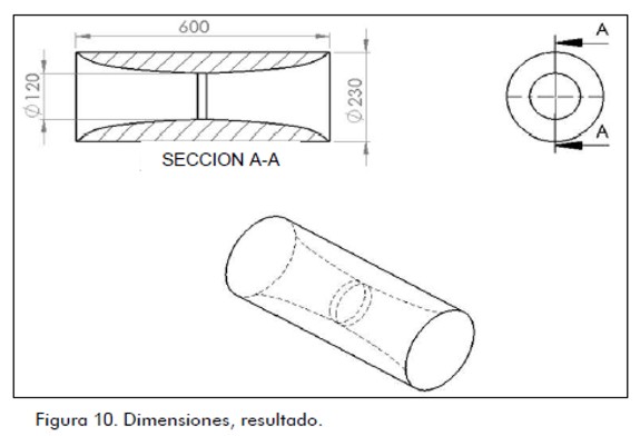
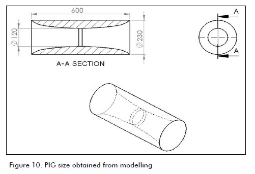
También, cada uno puede ser adecuado a un tipo de ducto o de fluido. Para la selección de una de las tres opciones del proyecto se utilizaron los mismos criterios de mínima fuerza y de máximo volumen; en consecuencia, la opción definida para el cuerpo del PIG es la de orificio con perfil de tipo bocal.
Las dimensiones propuestas para el PIG como resultado del proceso de optimización se presentan en la figura 10.
Referencias
Araújo A., Martins, P., Mota Soares, C. M., Mota Soares, C. A., Herskovits, J., Damping optimization of viscoelastic laminated sandwich composite structures., Structural and Multidisciplinary Optimization, Vol. 39, No. 6, December, 2009, pp. 569,579.
Boe, K., Pipeline PIG., Patent Application Publication. 0214590 A1 United States of America, September of 2007.
Frota, C., Inspeção com PIG instrumentado (MFL, geométrico e Inercial) no gasoduto Bolivia-Brasil., Neto. Anais da Rio Pipeline 2007 Conference, Instituto Brasileiro de Petróleo, Gás e Biocombustíveis (IBP), Outubro, 2007.
Korea Gas Corporation. R+D Division., Inteligent PIG. Details of research. En: http://www.kogas.re.kr/eng/index.jsp. últimoacceso: November de 2010.
Mattheus, L., Kennard, M. y O´Donoghue, A., Velocity control of pigs in gas pipelines., En: Pipeline Pigging and Integrity Technology, Scientific Surveys Ltd., 3401, Lousiana, Suite 255,Houston, TX 77002, USA, cap. 3, 2007, pp. 35-48.
Nguyen T. T., Yoo. H. R., Rho, Y. W., Kim, S. B., Speed control of pig using by-pass flow in natural gas pipeline., Proceedings of 2001 IEEE International Symposium on Industrial Electronics, IEEE Industrial Electronics Society, Pusan, Korea, 2001.
Pipeline Pigging Products and Services Association (PPSA)., Pigging terminology, abbreviations and formulae., En: http://www.ppsaonline.com/pigging-terms.php. último acceso: noviembre de 2010.
Podgorbunskikh, A. M., Devices for Automated Regulation of the Velocity of InTube Pig Flaw Detectors Review., Russian Journal of Nondestructive Testing, Vol. 44, No. 5, 2008, pp. 343 -350.
Stukenbruck, S., Notas do curso "Escoamento em Dutos"., Pontifícia Universidade Católica do Rio de Janeiro, 2008.
Evaluating drag force and geometric optimisation of pipeline inspection gadget (PIG) body with bypass
Ricardo Ramírez1, Max Dutra21 Mechanical Engineer, Department of Mechanical Engineering and Mechatronics, Universidad Nacional de Colombia, Colombia. reramirezh@unal.edu.co
2 Mechanical Engineering Program, COPPE, Federal University of Rio de Janeiro, Brazil. max@mecanica.coppe.ufrj.br
ABSTRACT
A pipeline inspection gadget (PIG) is a device used to run through pipelines for cleaning, measurement and inspection operations. By-pass is the name for one or a set of orifices allowing flow from back to front of a PIG. It is used for speed control or to improve cleaning operations results. By-pass prevents speed excursions in gas pipelines thereby avoiding damage to the PIG or the pipe. Studies and algorithms have been developed to simulate the dynamics of PIGs running inside pipes. Most studies have been for gas pipelines; these have helped to design some PIG models. This work summarises a particular stage during a PIG design project. This PIG will work in liquid pipelines and can stop in the line for inspection and maintenance tasks. Studying fluid force on a PIG when it has low or zero speed is needed for evaluating project feasibility and conceptual design. Selecting a PIG form to minimise the force of interaction with fluid allows a low weight design and lower energy loss.
Keywords: CFD, fluid structure interaction, optimisation, PIG, pipeline.
Introduction
Pipeline inspection gadget/gizmos (PIG) are self-contained devices, tools or vehicles moving through pipelines which are used in cleaning, sizing and inspection (PPSA, 2010) in petroleum and gas pipelines. PIG speed varies due to tube irregularities, changes in physical conditions between contact surfaces and variations in flow. Speed changes are greater in gas pipelines due to fluid compressibility and become dangerous for PIG or tube integrity. High acceleration phenomena are known as speed excursions Mattheus et al, 2007). The use of so-called by-pass orifices in a PIG' s body is one way to reduce speed excursions.
A bypass allows fluid passage from back to front of a PIG and the device' s displacement speed is different from average flow speed. Several studies have been aimed at designing PIGs having a by-pass (Nguyen et al, 2001; Boe, 2007; Korea Gas Corporation, 2010; Podgorbunskikh, 2008). In some cases, by-pass holes are used to form jets of the same fluid to enhance cleaning results; in other cases, a valve is added to the orifice and allows a PIG’s speed to be controlled (Frota, 2007).
A project has been designed for a PIG having special features like the ability to control speed and stop within a pipeline whilst fuel continues to be carried.
The starting concept for a PIG' s body is a cylinder having a central hole to act as a by-pass; the body is supported by polyurethane discs similar to those used in current cleaning PIGs. A valve is placed in the hole for controlling speed, stopping and starting; valve design was not included within the scope of this work.
The aim was to optimise cylinder shape and dimensions to achieve two goals: minimising the interaction force between fluid and body and maximising the body' s internal volume. The first goal would reduce mechanical design and control valve requirements; furthermore, it would reduce energy loss caused by the presence of a PIG in the pipeline. The second goal would create greater available internal volume inside the body so that items such as batteries, electronic boards and actuators could be placed there.
Procedure
Shape optimisation was performed in two stages. The first considered the by-pass hole having a constant diameter and optimum diameter was calculated whilst the second one involved the orifice profile being modified to correspond to various proposed forms for further reduction of the interaction force. The best profile and its optimal size were selected.
It was found during optimisation for the two stages, when varying PIG body dimensions, that if the interaction force was reduced then there was also a decrease in body volume. This meant that if a target were close to its optimum value when far away from its goal, the there were conflicting objectives and optimal diameter value was obtained by using the Pareto frontier concept (Araújo et al, 2009).
Materials and methods
General specifications
The model being studied consisted of a pipe segment and a PIG (Fig. 1). The pipe was cylindrical, straight and horizontal. Nominal project diameter was 12 inches, corresponding to 304.8 mm inner pipe diameter and 323.85 mm outer diameter having 4 m length and 25 micron internal roughness, typical of new steel pipe (Stukenbruck, 2008).

The model used to simulate a PIG was a cylinder having external protrusions simulating the scraping disks and had an axial hole whose shape and dimensions varied for the different cases to be simulated. The outer diameter corresponded to pipe diameter. The PIG length used was twice pipe diameter; this ratio is commonly used by PIG manufacturers and ensures that a PIG does not get stuck in pipeline bends.
The fluid selected was gasoline having r = 747 kg/m3 constant density and m = 6.57x10⁻⁴ Pa·s constant dynamic viscosity. The 5 m/s maximum flow speed corresponded to the flow speed typically used in pipelines carrying refined products.
Calculating optimum orifice diameter
Orifice diameter (DO) varied from 10% to 70% of the inner diameter of the pipe (DIT) in 10% steps. The force (F) exerted by the fluid on the PIG body in the direction of displacement was evaluated for each case using a computational fluid dynamics (CFD) tool. The result of force regarding DO/DI T ratio is presented in Figure 2 .
PIG body (VP) volume was also calculated for each case (Eq. 1).
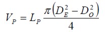 | [1] |
where, DE was the outer diameter of the PIG and LP its body length. The result is presented in Figure 3.

By increasing diameter, the force decreased and volume increased. As the aim was to minimise force and maximise volume, it was concluded that the two objectives conflicted. Orders of magnitude for force and volume were not comparable. Two functions f1 and f2 were defined for optimal diameter (Equations 2 and 3):
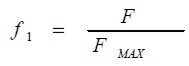 | [2] |
| | [3] |
Function f1 normalised force to a range from 0 to 1; f1 had to be minimised to minimise force f1. Function f2 normalised volume to a range between 0 and 1 to be comparable to f1 and f2 had to be minimised to maximise volume.
A new function was defined (Equation 4):
 | [4] |
C1 was design criterion by which the designer could give more or less importance to the objective of minimising force or maximising volume. C1 varied from 0 to 1 in 0.1 step. If C1 was small, it meant for the design that it was more important to maximise volume than minimise force and if C1 were large it meant the opposite.
Optimal diameter minimised function f for each value of C1. The results were presented on the Pareto frontier (Figure 4).
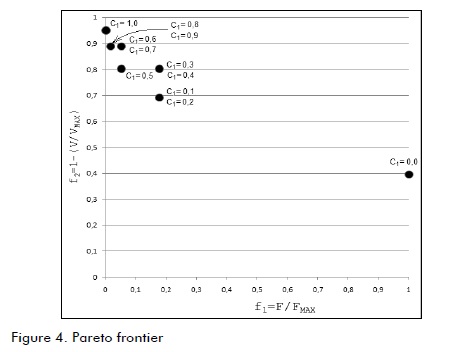
A criterion was selected that balanced the two objectives; it was C1 = 0.5. The optimal diameter for minimising the f function was 0.06 m or 60 mm.
Selecting and optimising orifice profile
Using a body having constant by-pass diameter caused the flow to have two abrupt changes in area: sudden contraction at the rear of the PIG and sudden expansion in front of it. Load loss could be reduced by modifying orifice profile to make contraction and expansion gentler.

Results
The force in all cases was calculated using CFD software. Volume was calculated using a geometric formula in the first profile and by integrating the solids of revolution for the second and the third profiles.
Results for the conical profile
The results of force and normalised volume function for the body for the conical profile are presented in Figure 6.
Results for the nozzle-type profile
The results of force and function for normalised volume for a nozzle-type profile are presented in Figure 7.
Results for the polynomial-type profile
The results of force for the polynomial-type profile are presented in Figure 8. The number of possible profiles was greater due to dependence on the six parameters. A genetic algorithm-type process was performed to obtain profiles having lower force. Sets of values r2, s1 and i2 were randomly generated (Figure 5(c)) and each set was used for calculating and building the corresponding profile. Force was calculated for this set of profiles. Profiles corresponding to cases having smaller force were selected and these profiles' parameters were crossed to create a second generation. Software runs were again made to calculate forces until an optimal profile was obtained.
The results of the normalised volume function are presented in Figure 9. The profiles calculated on the results were consecutively named P1 to P18.
Multi-objective optimisation was applied for each profile, similar to that described for obtaining optimal orifice diameter. An optimal variant for each type of profile was selected for each set of variants that minimised the force and maximised the volume. The value for the design criterion taken was: C1 = 0.5.
Table 1 shows the selected optimal variants with their corresponding values for force and available volume.
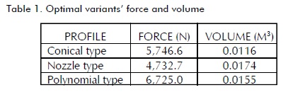
Analysis of results
Any one of these options provided a solution for building a PIG body. Each one provided the best combination of minimum force and largest available space for its particular type. Three models were built in the prototype construction stage and one was selected from experimental test results.
Also, each one may have been suited to one type of pipeline or fluid. The same criteria regarding minimum force and maximum volume were used to select one of three options for this work; hence, the definite choice for the PIG body was one having an orifice with a nozzle-type profile.
Proposed PIG size as a result of optimisation is presented in Figure 10.
References
Araújo A., Martins, P., Mota Soares, C. M., Mota Soares, C. A., Herskovits, J., Damping optimization of viscoelastic laminated sandwich composite structures., Structural and Multidisciplinary Optimization, Vol. 39, No. 6, December, 2009, pp. 569,579.
Boe, K., Pipeline PIG., Patent Application Publication. 0214590 A1 United States of America, September of 2007.
Frota, C., Inspeção com PIG instrumentado (MFL, geométrico e Inercial) no gasoduto Bolivia-Brasil., Neto. Anais da Rio Pipeline 2007 Conference, Instituto Brasileiro de Petróleo, Gás e Biocombustíveis (IBP), Outubro, 2007.
Korea Gas Corporation. R+D Division., Inteligent PIG. Details of research. En: http://www.kogas.re.kr/eng/index.jsp. últimoacceso: November de 2010.
Mattheus, L., Kennard, M. y O' Donoghue, A., Velocity control of pigs in gas pipelines., En: Pipeline Pigging and Integrity Technology, Scientific Surveys Ltd., 3401, Lousiana, Suite 255,Houston, TX 77002, USA, cap. 3, 2007, pp. 35-48.
Nguyen T. T., Yoo. H. R., Rho, Y. W., Kim, S. B., Speed control of pig using by-pass flow in natural gas pipeline., Proceedings of 2001 IEEE International Symposium on Industrial Electronics, IEEE Industrial Electronics Society, Pusan, Korea, 2001.
Pipeline Pigging Products and Services Association (PPSA)., Pigging terminology, abbreviations and formulae., En: http://www.ppsaonline.com/pigging-terms.php. último acceso: noviembre de 2010.
Podgorbunskikh, A. M., Devices for Automated Regulation of the Velocity of InTube Pig Flaw Detectors Review., Russian Journal of Nondestructive Testing, Vol. 44, No. 5, 2008, pp. 343 -350.
Stukenbruck, S., Notas do curso “Escoamento em Dutos”., Pontifícia Universidade Católica do Rio de Janeiro, 2008.
References
Araújo A., Martins, P., Mota Soares, C. M., Mota Soares, C. A., Herskovits, J., Damping optimization of viscoelastic laminated sandwich composite structures., Structural and Multidisciplinary Optimization, Vol. 39, No. 6, December, 2009, pp. 569,579. DOI: https://doi.org/10.1007/s00158-009-0390-4
Boe, K., Pipeline PIG., Patent Application Publication. 0214590 A1 United States of America, September of 2007.
Frota, C., Inspeção com PIG instrumentado (MFL, geométrico e Inercial) no gasoduto Bolivia-Brasil., Neto. Anais da Rio Pipeline 2007 Conference, Instituto Brasileiro de Petróleo, Gás e Biocombustíveis (IBP), Outubro, 2007.
Korea Gas Corporation. R+D Division., Inteligent PIG. Details of research. En: http://www.kogas.re.kr/eng/index.jsp. último acceso: November de 2010.
Mattheus, L., Kennard, M. y O’Donoghue, A., Velocity control of pigs in gas pipelines., En: Pipeline Pigging and Integrity Technology, Scientific Surveys Ltd., 3401, Lousiana, Suite 255, Houston, TX 77002, USA, cap. 3, 2007, pp. 35-48.
Nguyen T. T., Yoo. H. R., Rho, Y. W., Kim, S. B., Speed control of pig using by-pass flow in natural gas pipeline., Proceedings of 2001 IEEE International Symposium on Industrial Electronics, IEEE Industrial Electronics Society, Pusan, Korea, 2001.
Pipeline Pigging Products and Services Association (PPSA)., Pigging terminology, abbreviations and formulae., En: http://www.ppsaonline.com/pigging-terms.php. último acceso: noviembre de 2010.
Podgorbunskikh, A. M., Devices for Automated Regulation of the Velocity of InTube Pig Flaw Detectors Review., Russian Journal of Nondestructive Testing, Vol. 44, No. 5, 2008, pp. 343 -350. DOI: https://doi.org/10.1134/S1061830908050070
Stukenbruck, S., Notas do curso "Escoamento em Dutos"., Pontifícia Universidade Católica do Rio de Janeiro, 2008.
How to Cite
APA
ACM
ACS
ABNT
Chicago
Harvard
IEEE
MLA
Turabian
Vancouver
Download Citation
CrossRef Cited-by
1. Asghar Talbizadeh, Mohammad Mehdi Keshtkar. (2020). Numerical and experimental study on a bypass pig motion in oil transmission pipeline: a case study. Journal of Petroleum Exploration and Production Technology, 10(7), p.3007. https://doi.org/10.1007/s13202-020-00893-6.
Dimensions
PlumX
Article abstract page views
Downloads


License
Copyright (c) 2011 Ricardo Ramírez, Max Dutra

This work is licensed under a Creative Commons Attribution 4.0 International License.
The authors or holders of the copyright for each article hereby confer exclusive, limited and free authorization on the Universidad Nacional de Colombia's journal Ingeniería e Investigación concerning the aforementioned article which, once it has been evaluated and approved, will be submitted for publication, in line with the following items:
1. The version which has been corrected according to the evaluators' suggestions will be remitted and it will be made clear whether the aforementioned article is an unedited document regarding which the rights to be authorized are held and total responsibility will be assumed by the authors for the content of the work being submitted to Ingeniería e Investigación, the Universidad Nacional de Colombia and third-parties;
2. The authorization conferred on the journal will come into force from the date on which it is included in the respective volume and issue of Ingeniería e Investigación in the Open Journal Systems and on the journal's main page (https://revistas.unal.edu.co/index.php/ingeinv), as well as in different databases and indices in which the publication is indexed;
3. The authors authorize the Universidad Nacional de Colombia's journal Ingeniería e Investigación to publish the document in whatever required format (printed, digital, electronic or whatsoever known or yet to be discovered form) and authorize Ingeniería e Investigación to include the work in any indices and/or search engines deemed necessary for promoting its diffusion;
4. The authors accept that such authorization is given free of charge and they, therefore, waive any right to receive remuneration from the publication, distribution, public communication and any use whatsoever referred to in the terms of this authorization.