Formulating a design for a screwtype shear connector in a composite section
Maritzabel Molina Herrera1, Xavier Fernando Hurtado Amézquita2
1 Civil Engineer, Master in structures, Universidad Nacional de Colombia. Master of numerical methods for calculation and design engineering , Universidad Politécnica de Cataluña. Doctoral student in Structural Analysis , Universidad Politécnica de Cataluña. Associate Professor, Universidad Nacional de Colombia, Colombia. mmolinah@unal.edu.co
2 Civil Engineering and a Masters in engineering / structures. Universidad Nacional de Colombia, Colombia. xfhurtado@unal.edu.co
ABSTRACT
Screws-type shear connectors have been most used in Colombia during the last decade; however, an expression for their design in composite sections has only recently been presented (NSR10, paragraph F.2.9.8.2.2). This paper outlines shear design formulation development for screw connectors, analysing the influence of different composite section behaviour parameters. This research studied 18 composite section models using two 42MPa concrete slabs having different arrangements of 1/2", 5/8" or 3/4" diameter 1, 2 or 3 screw shear connectors and 0.08m, 0.12m or 0.14m spacing between connectors. Three specimens were tested by push-out for each model. The laboratory results using the methodology proposed by Ollgaard revealed connector diameter and spacing influence on the model’s behaviour. A design formulation for screws in composite sections is presented.
Keywords: shear connector, push-out test, shear design formulation, composite section.
Received: December 11th 2009
Accepted: July 15th 2011
Introduction
Screws have often been used as shear connectors in the Colombian construction sector during the last decade; however, an expression for designing them in composite sections has only recently been formulated.
AISC-LRFD specification [1] and previous Colombian standards for seismic-resistant design and construction (NSR-98) [2] design formulation only deals with channel and stud use as most research about connectors has been developed around these connectors. Such design standards establish that experiment tests must be carried out for determining their nominal strength as well as a design procedure. This paper presents deduction about screw-type connector design formulation (as per NSR-10, paragraph F.2.9.8.2.2) [3].
This paper provides a summary about research into specimens made with a steel (wide flange) W-beam section attached to two 42MPa concrete slabs which were tested with different configurations of 1, 2 or 3 screw-type shear connectors having 1/2", 5/8" or 3/4" diameters and 0.08m, 0.12m or 0.14m connector spacing. The specimens were tested by direct shear according to the push-out test method.
The experimental results were analysed according to screw stress, mainly by studying screw connector diameter and spacing influence on composite section behaviour. A screw design formulation has been proposed for use in composite sections made of concrete slabs and steel beams to ensure composite beams’ suitable performance.
Background
Ollgaard et al., [9] have proposed shear stress analysis for defining the behaviour of stud shear connectors in composite sections. Forty-eight push-out tests were used in which direct shear was applied to steel-stud-concrete interfaces, taking into account strength, modulus of elasticity, concrete density, aggregate type, diameter and number of studs per slab as analysis variables. Failure modes were concrete slab cracking, stud shear failure and combined damage.
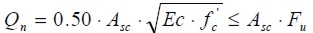
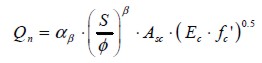
Stud behaviour analysis was based on the hypothesis that this is provided by uniform shear load distribution along a steelconcrete interface. The tests results led to formulating a stud connector design which appears in AISC-LRFD [1] and NSR-98 [2]:
| [1] |
where:
Qn: nominal stud connector shear strength [N]
Asc: nominal stud connector area [mm2]
f' c: compressive strength of concrete [mpa]
Ec: concrete' s modulus of elasticity [mpa]
Fu: ultimate stud connector tensile strength [MPa]
Bearing in mind the increase in Colombian construction work during the last decade where screws have been used as connectors in composite beams and whose structural designs have not been theoretically supported by suitable design methodology, Hurtado et al., [6] began to study this type of connector and analysed screw behaviour in composite sections made with steel W-beams. They carried out a push-out test on 18 configurations changing the number of connectors (1, 2 or 3), their diameters (1/2", 5/8" and 3/4") and the spacing between them. This work led to obtaining failure loads and assessed the loss of stiffness in all specimens by using load-slip curves. Hurtado et al., [6] also proposed a composite section design method for when screw connectors are used; they presented an equation for predicting shear load failure as follows:
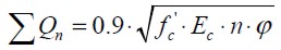 | [2] |
where:
SQn: nominal connector group shear strength [kN]
f' c: compressive strength of concrete [MPa]
Ec: concrete modulus of elasticity [MPa]
n: number of screw connectors in each system
f: connector diameter [m]
They also analysed proportionality between shear load failure and connector spacing, leading to the next relationship:
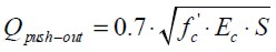 | [3] |
where:
Qpush-out : maximum push-out specimen shear load [kN]
f' c: compressive strength of concrete [MPa]
Ec: concrete modulus of elasticity [MPa]
S: spacing between stud connectors [m]
Garcia & Molina [5] carried out a bending test on 2 m length composite beams to check the above formulation proposed by Hurtado et al., which considered a concentrated load in the middle of the span. They studied 12 beams configurations in which the variables studied were concrete strength (21MPa and 28MPa), concrete modulus of elasticity, screw diameter (1/2", 5/8" and 3/4") and the spacing between connectors; there were 3 specimens for each configuration. According to experimental results, and Nie & Cai [8] and Burrnet & Oehlers' [4] theoretical analysis, the composite beams' behaviour concerned raising a load, flexural strength leading to shear load in connectors, beam deflection and steel-screw-concrete interface slip.
Garcia & Molina's [5] formulation of screw connectors analysed shear load on each screw produced by bending. This work was based on equation (3) proposed by Hurtado et al., [6], because the experimental results led to seeing the proportional relationship between the spacing between screws, shear load failure, compressive strength and concrete elasticity modulus.
Garcia & Molina [5] thus proposed the following equation (4) to predict maximum load per shear connector:
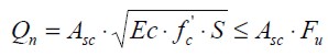 | [4] |
where:
Qn: nominal screw connector shear strength [N]
Asc: nominal screw connector area [mm2]
f' c: compressive strength of concrete [MPa]
Ec: concrete modulus of elasticity [MPa]
S: spacing between screw connectors [m]
Fu: ultimate tensile strength of the screw [MPa]
Figure 1 shows the plots for the equations proposed by Hurtado et al., [6] and Garcia & Molina [5]. That Figure shows the relationship between nominal shear load per screw and spacing between connectors, compared to tensile load and screw failure. The curves in this graph were constructed from the mechanical properties of the materials being tested (summarised in Table 2 and Table 3). A 1 ml length was taken in the formulation proposed by Hurtado et al., [6] for providing an objective comparison between screw loads. Expression (2) was thus rewritten as:
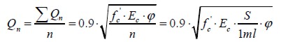 | [5] |
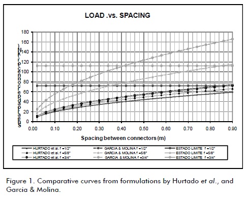
The difference between formulations is shown in Figure 1. Some researchers took shear load in push-out specimens into account and others based their approach on shear flow distribution by bending composite beams. Experimental results must be compared to other methods to standardise data test and thereby to optimise formulating screw connector design.
The method proposed by Ollgaard et al., [9] was used for analysing the experimental results obtained by Hurtado et al., [6] to study the influence of different variables on connector behaviour based on screw stress for obtaining a suitable design formulation.
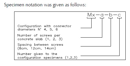
Figure 2 shows specimen geometry. The specimens were made from two 0.30m high, 0.50m long and 0.10m thick concrete slabs attached to IPE200 steel beam flanges with 1/2", 5/8" and 3/4" diameter screw connectors having 0.08m, 0.12m and 0.14m spacing between them. The number of connectors was varied to use 1, 2 or 3 screws. There were thus 18 configurations for 54 specimens. Screw connectors were welded to a steel profile but weld properties were not considered in this analysis.
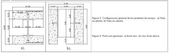
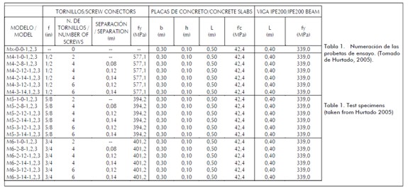
Table 1 gives a description of the specimens tested.
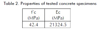
Materials
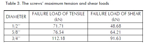
Experimental tests included concrete modulus of elasticity, concrete strength, screw connector tension and shear strength. Experimental results are listed in Tables 2 and 3. This data was used to analyse the specimens' behaviour as composite systems.
Push-out test setup
Push-out tests have been carried out since 1956; they were initially used by Viest [10] in research into connectors. Axial load was applied to the top of a steel profile until failure occurred so that shear stress was only transferred through the connectors; therefore, the effect of shear direct became isolated, as shown in Figure 3.
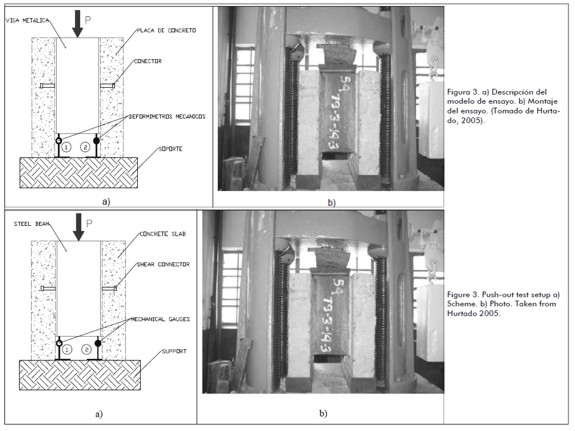
Two mechanical gauges located at the bottom of the IPE200 profile were used for measuring average displacement and to check whether any profile rotations occurred during the pushout test (Figure 3).
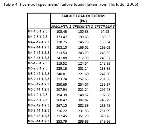
Results
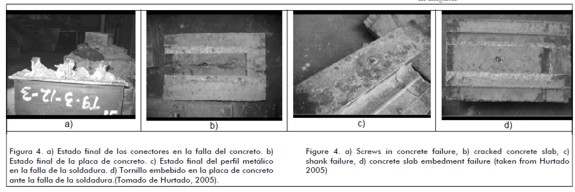
Table 4 lists ultimate loads. Regarding experimental results, the predominant failure mode involved one of the concrete slabs cracking with screw deformation appearing in 80% of all tests in specimens having two or three connectors (Figure 4a and 4b). Failure was produced by the weld shearing off in the other 20% (Figure 4c and 4d) but screw shear strength was never exceeded as found in tests carried out on the screws (Table 3).
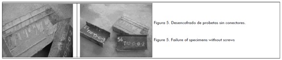
While formworks stripped off specimens without connectors, the concrete slabs split from the steel beam (Figure 5); the adherence between steel profile and concrete slab could thus not be measured. However, such failure proved that friction between steel and concrete should not be considered for an optimal connector design and that the interaction between these materials in composite sections must be fully ensured by the shear connectors.
This work was based on the hypothesis that in composite beams having lower concrete strength than 42 MPa and screw connector strength greater than or equal to grade two, then the main failure mode would be concrete slab cracking in view of the failure modes presented in the push-out tests and that the strength of concrete obtained from material tests was 42MPa. This would have depended on proper screw connector design and suitable application of welding around the connector.
This research adopted a different approach to formulation based on average loads used by Hurtado et al., [6]. The method proposed by Ollgaard et at., [9], stating that screw shear stress should be analysed assuming uniform shear flow distribution between them, was adopted and thus all experimental data were normalised on the same scale, regardless of screw separation and number. This methodology extended the overview of comparing different configurations.
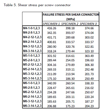
All 54 specimens were studied without considering average values for optimising screw connector design formulation because they may have been influenced by spurious data depending on three specimens' average behaviour, and therefore affected screw performance analysis. The stress values are listed in Table 5.
At the beginning of this analysis, specimen behaviour was compared in terms of screw shear stress caused by load failure. The Qu/Asc, cf S graph (Figure 6) was drawn up to assess the influence of screw diameter and spacing and link these variables to a general expression for screw connector design.
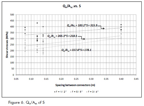
Figure 6 shows that connector shear stress was greater when screw diameter was less, regardless of screw spacing and the number used. It also shows the relationship between shear stress and spacing for each diameter; screw stress was lower for smaller separations. This was also in Hurtado' s thesis [7] stating that load -slip curves show that the smaller the screw diameter, the greater section degradation stiffness.
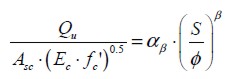
Based on Garcia & Molina [5] who proposed formulation (3), and taking into account the relationship between screw connector shear stress, spacing and diameter, the following formulation was stated:
 | [6] |
This equation allows compressive strength to be linked to the elasticity modulus of concrete, along with connector shear stress and S/f relationship in an easily applicable manner.
Equation (7) was considered where equation (6) was otherwise arranged and exponential regression was done from experimental data. These results are shown in Figure 7 .
 | [7] |
Two regressions are shown in Figure 7 in view of the variability of information for the 54 specimens; the first assessed all experimental results and the other excluded extreme upper and lower values (i.e. top and bottom 5%).
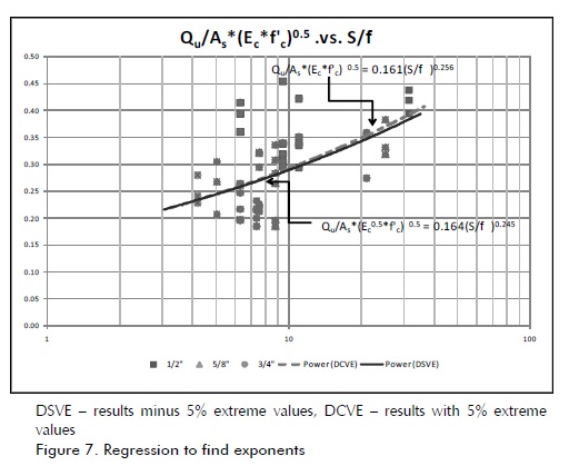
According to the regression curves, b=0.25 was adopted due to this coefficient having little variation and allowing easy handling of the formulation.
The next step was to find out the value of slope a25. Linear regression was done (Figure 8) with and without extreme data. The values for coefficient a25 were 0.143 and 0.164, given in the following equations:
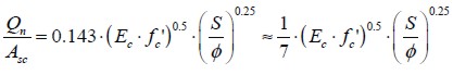 | [8] |
 | [9] |
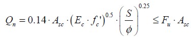
a25=0.14 was thus taken. It was considered that the relationship crossed through point (0,0) of the graph for designing the equation so as to disregard the adherence effect between steel profile and concrete slab because the frictional strength between these elements was negligible. The general equation proposed in this research was thus:
 | [10] |
where:
Qn: nominal screw connector shear strength [N]
Asc: nominal screw connector area [mm2]
f' c: compressive strength of concrete [MPa]
Ec: concrete modulus of elasticity [MPa]
f: connector diameter [mm]
S: spacing between stud connectors [mm]
Fu: ultimate screw tensile strength [MPa]
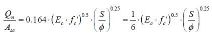
Design equation (10) (shown in Figure 9) had 21MPa and 28MPa compressive strength for concrete and 1/2", 5/8", 3/4" and 7/8" connector diameter. Such materials are often used in Colombian construction work.
This Figure confirms the relationship between screw diameter, concrete' s compressive strength and screw connector shear load. It may thus be concluded that specified composite screw spacing may lead to greater nominal screw load and increasing connector diameter may lead to increased concrete compressive strength or a combination of both These measurements may also improve composite beams' steel-screw-concrete interface behaviour.
Connector spacing also exerts an important influence on composite section shear strength. If the spacing between screws is increased, each connector will be subjected to a heavier load. Screws could thus have inelastic behaviour with permanent deformations where shear load distribution in the set of screws will not be uniform (thereby going against this work' s initial hypothesis).If screw spacing is reduced, then design will become very expensive and system efficiency will be reduced because screw performance will become limited by overlapping afferent areas. Given that the NSR only sets guidelines for stud spacing, screw spacing should be studied to define minimum and maximum allowable values in design.
Conclusions
The approach adopted in this paper for designing screw connector formulation regarding screw shear stress led to a detailed study of screw performance in composite sections.
Taking into account the variables involved in this study, the proposed design equation is:
 |
Specimens lacking connectors showed that concrete slab adherence to steel profile was negligible, so friction strength should be disregard when ascertaining composite section shear strength. Shear stress transfer between concrete and steel must thus only be ensured by shear connectors.
Nomenclature
Asc = nominal screw connector area [mm2]
Ec = concrete modulus of elasticity [MPa]
f'c = compressive strength of concrete [MPa]
S = spacing between connectors [mm]
f = screw connector diameter [mm]
Fu = ultimate screw tensile strength [MPa]
Qn = nominal screw connector shear strength [n]
aβ = correlation coefficient of the slope given a β coefficient
b = the relationship' s coefficient of correlation (S/f)
Acknowledgements
This research' s first phase was financed by the Universidad Nacional de Colombia' s Research Division (DIB) (20201005550, Resolution 70 February 10th, 2005).
References
American Institute of Steel Construction., Specification for Structural Steel Buildings, Chicago, 2005.
Asociación de Ingeniería Sísmica., NSR-98, Tomo 3, Bogotá, 1998, pp. F38-F39.
Asociación de Ingeniería Sísmica., NSR-10, Título F, Bogotá, 2010, pp. F102-F103.
Burnet, M., Oehlers D., Fracture of Mechanical Shear Connectors in Composite Beams MECH., STRUCT & MACH, 2001,pp. 1-41.
García, A., Molina, M., Comportamiento de vigas de sección compuesta con perfiles de acero laminado y losa de concreto empleando conectores de cortante tipo tornillo grado dos (2)., Ingeniería e Investigación, 2008, pp. 11-21.
Hurtado, X., Molina, M., Linero, D., Comportamiento de conectores de cortante tipo tornillo de resistencia grado dos para un sistema de sección compuesta., Ingeniería e Investigación, 2008, pp. 4-14.
Hurtado, X., Comportamiento de conectores tipo tornillo grado dos para un sistema de sección compuesta con concreto de 21MPa ante solicitación de corte directo., Tesis de Magister en Ingeniería- Estructuras, Universidad Nacional de Colombia, 2007.
Nie, J., Caí, C., Steel-Concrete Composite Beams Considering Shear Slip Effects., Journal of Structural Engineering, Vol. 129, 2008, pp. 4-14.
Ollgaard, J., Slutter, R., Fisher, J., Shear strength of stud connectors in lightweight and normal-weight concrete., Engineering Journal, AISC, 1971, pp. 55-64.
Viest, I., Investigation of stud shear connectors for composite concrete and steel t-beams., Journal of the American Concrete Institute, ACI, 1956, pp. 875-890.