
MEDIDAS DE EFECTO HALL Y RESISTIVIDAD EN ALEACIONES MAGNÉTICAS AMORFAS BASADAS EN CoFe
HALL EFFECT AND RESISTIVITY MEASUREMENTS IN CoFe–BASED AMORPHOUS MAGNETIC ALLOYS
Jhon Melo–Quintero, Andrés Rosales–Rivera, and Helver Giraldo–Daza
Laboratorio de Magnetismo y Materiales Avanzados, Facultad de Ciencias Exactas y Naturales, Universidad Nacional de Colombia Sede Manizales, A.A. 127
Contacto: Jhon Melo–Quintero shonmelo@hotmail.com
Contacto: Andrés Rosales–Rivera arosalesr@unal.edu.co
Contacto: Helber Giraldo–Daza hagiraldod@unal.edu.co
(Recibido: 10/2010. Aceptado: 12/2010)
Cómo citar: Melo–Quintero, J., Rosales–Rivera, A., Giraldo–Daza, H., Momento, 41, 37 (2010)
Resumen
En este trabajo, presentamos el diseño y la automatización de un sistema de medición de efecto Hall de corriente directa (DC) y corriente alterna (AC) usando un método de cuatro puntas. Este sistema consiste en una fuente de corriente directa y alterna (Modelo 6221 CD–CA, Keithley Instruments Inc.) acoplada a un nano–voltímetro (Modelo 2182 A, Keithley Instruments Inc.), y un electroimán (Phylatex) que proporciona campos magnéticos de hasta 0,8 T. Este sistema tiene varias capacidades de medición incluyendo voltaje Hall, coeficiente Hall, resistencia, resistividad y curvas I–V, y puede funcionar en los modos de corriente directa CD y alterna CA (hasta 10 Hz). El funcionamiento del sistema de medición de efecto Hall fue verificado usando una muestra patrón de cobre y varios circuitos de resistencia que corresponden a muestras simuladas de materiales metálicos y semiconductores. Este sistema fue utilizado para estudiar las propiedades de magneto–transporte a temperatura ambiente de las cintas amorfas magnéticas blandas Co64Fe21B15 y Co71Fe4B15Si10. Finalmente, presentamos un análisis de esas propiedades de magneto–transporte.
Palabras claves: Cintas de materiales magnéticos amorfos, Conductividad eléctrica.
Abstract
In this paper, a design and automation of a DC and AC Hall effect measurement system using a four–wire method is presented. This system consists of a Current Source (Model 6221 DC–AC, Keithley Instruments Inc.) connected to a Nanovoltmeter (Model 2182A, Keithley Instruments Inc.), and an electromagnet (Phylatex) that provides magnetic fields up to 0.8 T. This system has several measurement capabilities including Hall voltage, Hall coeficient, resistance, resistivity, and I–V curves, and can be operated in both DC and AC (up to 10 Hz) current modes (IAC, IDC). The functioning of the Hall effect measurement system was verified using both a standard sample of copper and several resistor circuits that correspond to simulated metallic and semiconductor samples. This measurement system was used to study the magneto–transport properties at room temperature of the soft magnetic amorphous ribbons Co64Fe21B15 and Co71Fe4B15Si10. An analysis of these magneto–transport properties is presented, too.
Keywords: Hall Effect instrumentation, amorphous magnetic materials – ribbons, electrical conductivity
Introduction
The Hall effect [1], as an experimental technique, is very useful in probing the nature of electrical conduction in materials. The technique is based on the well–known fact that when a magnetic field is applied to a current–carrying solid material, perpendicular to the current direction, then a potential (named the Hall voltage) is produced up crossing the solid material. The usual method used in Hall effect measurement, generally, uses a DC electric field (DC Hall effect) in order to induce the electric current in the solid material under study. This method has been applied successfully to a wide range of materials including metals and semiconductors. Measurement of Hall voltage in materials with low mobility, however, is a hard task due to the fact that Hall voltage is very small (on the order of μV), and it is necessary to use methods, which take into account the possibility of performing stable, low noise voltage measurements. In this context, Hall effect measurement methods using AC electric field (AC Hall effect) are now gaining attention, as a complement to DC Hall methods [2]. Here we have interest in using the Hall effect in order to study materials such as CoFe–based amorphous magnetic alloys that are mainly applied to highfrequency transformers and magnetic recording heads, due to their high magnetic permeability and vanishing magnetostriction constant. At high–frequencies applications, it is necessary to reduce the eddy current losses that are associated to the material's resistivity, ρ. Until recently, most of the studies of these alloys [3–7] were focused on the magnetization, permeability, giant magneto–impedance effect, structural state, thermal properties, crystallization processes, heat treatment and their influence to the control of induced magnetic anisotropy. Only a few studies on Hall effect [2] and AC susceptibility [2, 8] have been carried out in these materials. It is, therefore, important to know the nature of electrical conduction in these materials. Hall voltage along with a resistivity measurement provides insight into the transport mechanism in materials. The main purpose of this paper, in addition to constructing a DC and AC Hall effect and resistivity measurement system, is to gain knowledge on the electric transport properties of the soft magnetic amorphous ribbons Co64Fe21B15 and Co71Fe4B15Si10. These electrical properties will be analyzed within the context of Drude's model.
Experimental assembly
There is an extensive literature on the different methods of implementing a Hall effect and resistivity measurement system, its associated problems and how to overcome them [9–16]. Here we present a brief description about the construction of an DC and AC Hall effect and resistivity measurement system together with our solutions to the problems that arise in their construction such as offset voltage and measuring of small voltages. The Hall effect and resistivity measurement system setup implemented in the present work is illustrated in Fig. 1, and it has three experimental facilities automated with self written codes in LabView language: (1) DC Hall effect measurement system using the four–wire method, (2) DC van der Pauw method, and (3) AC Hall effect measurement system using AC electric current. This system consists of a Current Source (Model 6221 DC–AC, Keithley Instruments Inc.) connected to a Nanovoltmeter (Model 2182A, Keithley Instruments Inc.), and an electromagnet (Phylatex) that provides magnetic fields up to 0,8 T. In a Hall effect measurement system it is necessary to minimize the offset voltage due to misalignments in the two voltage probes, sample shape, and sometimes non–uniform temperature. This problem was overcome by performing two sets of Hall measurements, one in the positive magnetic field direction and other in the reverse direction, and the Hall voltage was evaluated as the average value of these two measurements. Another source of offset voltage is due to photovoltaic and photoconductive effects. This problem was controlled by placing the sample under study in a dark environment. The Hall voltage in metals, generally, is very small (on the order of μV) due to its high concentration of charge carriers. In order to control this problem, we employed a Model 2182A Nanovoltmeter as discussed above, which allowed us performing stable, low noise voltage measurements.
Figure 1. Block diagram of the Hall effect measurement system implemented in the present work
Results and Discussions
In magnetic materials, the Hall effect involves two contributions that can be considered for using the empirical equation for the Hall resistivity,
![]()
where H is the magnetic field, M is the magnetization, and Ro and Re are the ordinary and extraordinary Hall coeficients, respectively. In Eq. 1 the first term is due to the Lorentz force acting on the charge carriers. The second term depends on the magnetization. In the low–field limit, Ro is given by Ro = —1/ne [16] and thus, n = 1/|Ro|e, being n the carrier concentration and e the electron charge. As it is well–known [9, 10], in terms of experimentally determined quantities, Ro can be expressed as
![]()
where VH is the Hall voltage, d is the thickness of the sample, H is the magnetic field applied to the sample, and I is the current flowing in the sample. From Hall voltage and resistivity curves we can obtain several physical parameters of materials including Hall coeficient, resistivity, concentration and mobility of charge carriers, besides mean free path of charge carriers and relaxation time. The time relaxation can be determined by using the resistivity (ρ)and the carrier concentration,
![]()
where me is the electron mass (free–electron model). The charge mobility and the mean free path are respectively give by μ = |e/me|τ and l = ⟨νo⟩τ, where ⟨νo⟩ is the mean electronic speed. In the Drude's model, ⟨νo⟩ was considered to be the mean thermal velocity of an electron given by ⟨ντ⟩ = (3KBT/me)1/2 and at T = 293 K this corresponds to ⟨ντ⟩ = 1,2 × 107 cm/s.
The results for Hall voltage vs. H in Co64Fe21B15 and Co71Fe4B15Si10 are displayed in Fig. 2a and b for IDC ranging from 1,43 to 10 mA at room temperature, for comparison. Notice that
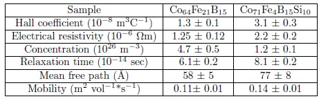
Table 1. Values of several physical parameters for Co64Fe21B15 and Co71Fe4B15Si10 obtained from Hall voltage vs. H data for IDC = 10 mA at room temperature
Hall voltage in both samples is very small (on the order of or lower than 2 μV). Another feature observed in Figs. 2a and b is a quite linear behavior of Hall voltage as a function of applied magnetic field, indicating that the magnetization is not saturated yet. In agreement with the contributions to the Hall effect mentioned above, the Hall voltage curves are expected to exhibit a change of gradient. This behavior, however, is absent due probably to the fact that the magnetization in these samples saturates at a much higher than those used in our experiments (on the order of 2 kOe). The magnetization, for instance, saturates at a field value of 7, 17, and 21 kOe in Co70Fe5Si15B10 [2], Co [9], and Fe [9], respectively. It can be noted by inspection of data in Fig.2a and b that the Hall coeficient is positive indicating that the charge carriers in both samples have a positive character.
This positive sign of the Hall coeficient is in agreement with the positive sign of the Hall coeficient observed in Co and Fe. Besides, these Hall coeficient values (on the order of +10—8 m³C—1, see table 1) are lower than the typical values (on the order of +10—3 m³C—1) measured in semiconductors [17, 18] but larger than those measured in metals, as such iron (+1, 10 × 10—9 m³C—1)[9], cobalt (+2,5 × 10—10 m³C—1) [9], and Cu (—5,3 × 10—11 m³C—1)[17, 18]. Since the value of Hall coeficient is a reflection of the several different kinds of atom that constitute the alloys thus, one could expect that the Hall coeficient value in both samples falls somewhere in between values corresponding to semiconductors and metals materials.

Figure 2. (a,b): Hall voltage vs. H in Co64Fe21B15 (a) and Co71Fe4B15Si10 (b) at several current values.
The results obtained from Hall voltage and resistivity measurements at room temperature and IDC = 10 mA for several physical parameters in the Co64Fe21B15 and Co71Fe4B15Si10 samples are displayed in table 1. It is found that the carrier concentration (on the order of 1026m—3) in both samples is two orders of magnitude lower

Figure 3. (a,b): Hall voltage vs. current in Co64Fe21B15 (a) and Co71Fe4B15Si10 (b) at several current values.
than the 1028m—3 typical of simple metals, implicating that both samples have a semi–metallic behavior, but the carrier concentration in the Co71Fe4B15Si10 sample is lower than that in the Co64Fe21B15 sample. The resistivity in both samples is two orders of magnitude larger than the 10—8 Ωm typical of simple metals at room tem–

Figure 4. (a,b): In–phase (a) and out–of–phase (b) components of the AC Hall voltage as a function of the applied magnetic field in Co64Fe21B15 for IAC = 10 mA and f = 257, 505, and 1000 mHz at room temperature.
perature, as expected for alloys, but the Co71Fe4B15Si10 sample is more resistive than the Co64Fe21B15 sample at room temperature, in agreement with the Hall voltage results and the presence of Si. Again, both samples have a semi–metallic behavior.
Based on the positive sign of Hall coeficient, and the values obtained for the carrier concentration and resistivity, we might think that electrons occupying orbitals near the band maximum are the main charge carriers in both samples. The relaxation time is slightly longer than the 2 × 10—14 sec typical of Cu at room temperature but is on the order of 1010—14 sec. On the other hand, the mean free path in both samples is slightly longer than the 30 Å typical of Cu at room temperature (within framework of Drude's model), for example, but the mean free path in the Co71Fe4B15Si10 sample is slightly longer than that in the Co64Fe21B15 sample. Moreover, very similar values for all above physical parameters were also obtained from Hall voltage vs. IDC data for H ranging from 20 to 120 mT at room temperature (see Fig. 3a and b), within of the experimental error of our Hall effect measurement system.
The in–phase and out–of–phase components of the AC Hall voltage as a function of the applied magnetic field in Co64Fe21B15 for IAC = 10 mA and f = 257, 505, and 1000 mHz at room temperature are displayed in Fig. 4a and b, respectively. All the in–phase data fall on a single curve as it is clearly seen in Fig. 4a. In addition, the in–phase data follow a quite linear behavior as a function of applied magnetic field. This behavior is consistent with the field dependence of the DC Hall voltage, as discussed above (see Fig. 2). All the out–of–phase data also fall on a single curve with a small phase shift around to zero. Since the Hall phase shift vanishes in the DC limit, the scatter of the points –on the order of ± 4°) shows directly the noise that affects our measurements.
Conclusions
We developed and automated a DC and AC Hall effect measurement system using a four–wire method with a program written in LabView language. This system did allow us to study the electrical nature of CoFe–based amorphous magnetic alloys. It was found that the soft magnetic amorphous ribbons Co64Fe21B15and Co71Fe4B15Si10 have a semi–metallic behavior. The Co71Fe4B15Si10sample is more resistive than the Co64Fe21B15 one at room temperature, in agreement with the Hall voltage results and the presence of Si.
Acknowledgements
This study, carried out at the Universidad Nacional de Colombia, Branch of Manizales, was supported by the Research Office (DIMA) under Project No 20201005452.
References
[1] E. Hall, Amer. J. Math. 2, 287 (1879).
[2] L. Gonçcalves, J. Soares, F. Machado, and A. Rodrigues, J. Non–Cryst. Solids 352, 3659 (2006).
[3] M. E. McHenry, M. A. Willard, and D. E. Laughlin, Prog. Mater. Sci. 44, 291 (1999).
[4] M. Vázquez, J. Magn. Magn. Mater. 226–230, Part 1, 693 (2001).
[5] M. Knobel and K. Pirota, J. Magn. Magn. Mater. 242–245, Part 1, 33 (2002).
[6] M. Knobel, M. Vázquez, and L. Kraus, in Handbook of Magnetic Materials, Handbook of Magnetic Materials, Vol. 15, edited by K. Buschow (Elsevier, 2003) pp. 497 — 563.
[7] A. Rosales–Rivera, V. Valencia, and P. Pineda–Gómez, Physica B 398, 252 (2007).
[8] A. Rosales–Rivera, O. Moscoso–Londoño, and D. Muraca, "Magnetization dynamics and magnetic hardening in amorphous febsi alloys," (2011), to be published in the Journal Mexican of Physics.
[9] G. B. Armen, Hall Effect Experiment (The University of Tennessee, Department of Physics and Astronomy, 401 Nielsen Physics Building, 2007).
[10] W. R. Thurber., Physical measurement laboratory: Hall Effect, Tech. Rep. (NIST, 100 Bureau Drive, MS 8120. Gaithersburg, MD 20899–8120, 2008).
[11] R. Green, Hall Effect Measurements in Materials Characterization, White paper No. 3111 (Keithley Instruments, Inc., 2011).
[12] A. F. . Standard, Test Methods for Measuring Resistivity and Hall Coefocient and Determining Hall Mobility in Single–Crystal Semiconductors, Tech. Rep. (ASTM International, West Conshohocken, 2011).
[13] L. J. van der Pauw, A Method of Measuring Specific Resistivity and Hall Effect of Discs of Arbitrary Shapes, Vol. 13 (Philips Res. Repts, 1958) pp. 1–9.
[14] L. J. van der Pauw, A Method of Measuring the Resistivity and Hall Coeficient on Lamellae of Arbitrary Shape, Vol. 20 (Philips Tech. Rev., 1958) pp. 220–224.
[15] E. Putley, The Hall effect and related phenomena, Semiconductor monographs (Butterworths, 1960).
[16] C. Hurd, The Hall effect in metals and alloys, International Congresses of Quantum Chemistry Series (Plenum Press, 1972).
[17] Leybold, "Hall effect in metals," PHYWE series of publications. Laboratory experiments (2010).
[18] R. Adler, A. Smith, and R. Longini, Introduction to Semiconductor Physics, Seec Notes, Vol. 1 (J. Wiley & Sons., 1964).