Publicado
THE STRUCTURE OF THE COMPUTATIONAL SIGNAL ALGEBRA AND ITS APPLICATION IN DIGITAL IMAGE PROCESSING
Palabras clave:
Signals space, digital images, signal algebra, mathematical structure, digital signal processing. (es)
THE STRUCTURE OF THE COMPUTATIONAL SIGNAL ALGEBRA AND ITS APPLICATION IN DIGITAL IMAGE PROCESSING
LA ESTRUCTURA DEL ÁLGEBRA DE SEÑALES COMPUTACIONAL Y SUS APLICACIONES EN PROCESAMIENTO DE IMÁGENES DIGITALES
MARLIO PAREDES
Professor, School of Science and Technology, Universidad del Turabo, Puerto Rico, USA, maparedes@suagm.edu
JORGE VILLAMIZAR MORALES
Escuela de Matemáticas, Universidad Industrial de Santander, jorge@uis.edu.co
LOLA XIOMARA BAUTISTA ROZO
Automated Information Processing Laboratory, University of Puerto Rico at Mayaguez, lola.bautista@ece.uprm.edu
DOMINGO RODRIGUEZ
Professor, ECE Department University of Puerto Rico at Mayaguez, Puerto Rico, USA, domingo@ece.uprm.edu
Received for review August 10th, 2009, accepted October 13th, 2010, final version October, 22th, 2010
ABSTRACT: This work starts from the knowledge of the mathematical structure of the signals space used in signal processing and provides the development of a computational theoretical framework of signal algebra for modeling and processing applications using digital images. The mathematical structures were implemented over computational structures using the Java programming language as a tool for the coding of the algorithms. The implemented tool was called JCID (Java Computational Image Developer), which allows for one to implement several of the operators from the signal algebra for one-dimensional and two-dimensional signals, and the creation of new entrants through the composition of the basic operators.
KEYWORDS: Signals space, digital images, signal algebra, mathematical structure, digital signal processing.
RESUMEN: Este trabajo se inicia a partir del conocimiento de la estructura matemática del espacio de señales usado en el procesamiento de señales y provee el desarrollo de un marco teórico computacional de álgebra de señales para el modelamiento y procesamiento de aplicaciones usando imágenes digitales. Las estructuras matemáticas fueron implementadas sobre estructuras computacionales usando el lenguaje de programación Java como una herramienta para la codificación de los algoritmos. La herramienta implementada fue llamada JCID (Java Computational Image Developer), la cual permite implementar varios de los operadores del algebra de señales para señales de dimensión uno y dimensión dos, y la creación de nuevas entradas a través de la composición de los operadores básicos.
PALABRAS CLAVE: Espacio de señales, imágenes digitales, algebra de señales, estructura matemática, procesamiento de señales digitales.
1. INTRODUCTION
Digital signal processing and image processing are techniques used in different fields such as hydrology and medicine. Although the conditions of acquisition of data are completely different, most of the final outputs displayed to a user are relatively seamless. Also, most of the techniques used to do processing in one of them is also used in the other. For example, applying filters for image enhancement is a common tool that is available in specialized software for either hydrology or medicine.
The advantage of creating a Computational Signal Processing System that deals with the algorithmic treatment of signal-based data is that, independent of the kind of data or its source, the data can be processed by standard methods established by a formal mathematical notation which can be translated to any programming language. In this work, Digital Signal Processing (DSP) techniques are used to represent the signals mathematically and get the information carried by them. The mathematical basis of DSP algorithms lies in the set theory, group theory, and algebraic structures concepts which can be applied to the fields of real numbers ( ) and complex numbers (
 ).
).
Signal algebra is constructed by using binary two-dimensional cyclic convolution as the product operation that turns a linear space of two-dimensional finite discrete images into linear algebra. Matrix representations of two-dimensional cyclic convolution operations are represented as block circulant matrices with circulant blocks [1]. This is accomplished when finite discrete image object arrays, serving as inputs in the matrix-vector computation of the two-dimensional cyclic convolution operation, are transformed into one-dimensional column vectors by using both lexicographic and anti-lexicographic ordering. Special attention is given to the algebra of cyclic correlations which is related to the algebra of cyclic convolutions through the index reversal or reflection operator. Some basic DSP concepts such as the definition of one-dimensional signal space, its algebraic structure, and the operators that act over this space are presented [2]. All these concepts are generalized later to two-dimensional signal space.
2. SIGNAL ALGEBRA
The mathematical concepts and results presented in sections 2, 3, and 4, were studied in detail in [3].
Definition 1: A function whose domain is a discrete set will be called a discrete function. Here, every discrete function will be called a discrete signal.
Definition 2: A function whose codomain is a discrete finite set is called a digital signal. If the codomain is the set of complex numbers, it is said that the signal is a complex discrete of dimension  .
.
Definition 3: Let  be a field and let
  and
and  be two algebras over
  . An isomorphism between the algebras
  and
and  is a bijective function
  such that
1.  ,
,
2.  ,
,
for all  and all
  . Notice that the first condition establishes that an isomorphism of algebras is an isomorphism of vector spaces which, in addition, preserves the products.
Definition 4: A circulant matrix of order  is a square matrix of order
  of the form

The elements of each column (row) of  are identical to those of the previous column (row), but they are moved one position up (left) and wrapped around. So the whole matrix is determined by the first column (or row). Also, it may occur that the entries move going down, and in this case the matrix has the form

Let  be square matrices each of the order
  . By a block circulant matrix of type
  (and of the order
  ) is meant an array of order
  which has the form
 ,
,
where each entry  is a circulant matrix.
Definition 5: The simplest relation between a finite-length sequence  , defined for
  , and its discrete-time Fourier transform (DTFT)
  is obtained by uniformly sampling
  on the
  -axis between
  at
at  ,
,  and it is usually written:
 ,
,
where  . Note that
  is also a finite-length sequence in the frequency domain of length
  . The sequence
  is called the discrete Fourier transform (DFT) of the sequence
  . According to the commonly used notation
  , we can rewrite the DFT of
  as
as
 .
.
The inverse discrete Fourier transform (IDFT) of  is given by
 .
.
3. THE SPACE OF ONE-DIMENSIONAL SIGNALS
Definition 6: A one-dimensional signal is a function

An equivalent form to denote a signal is as a sequence of complex numbers  . It is common to write a signal as a column vector

The space of one-dimensional signals is denoted by  . This space has a vector space structure over the complex numbers with the sum of functions and the multiplication by a scalar [3]. A basis for this signal space is the set
 ,where the functions
  are defined by

This is the standard basis for  .
.
Definition 7: The cyclic convolution operation over the space of one-dimensional signals is defined as follows:
 ,
,
where  is defined by

The cyclic convolution has the following properties for  and
and  :
:
1.  .
.
2.  .
.
3. 
4.  .
.
With all the previous properties, the following result can be obtained.
Theorem 1: The space of one-dimensional signals  is a commutative algebra using the cyclic convolution as multiplication.
Now, let's represent the cyclic convolution as an operator over the signal space  . Let
. Let  and
and  , then we obtain the following system
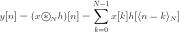 ,
,
where  . This system can be written as
  , where
 and
and
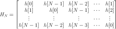
Fixing  , the cyclic convolution operation becomes a linear operator acting over the signals space which is called the cyclic convolution operator. This operator is denoted by
  and defined as

The matrix of this operator is  which is a circulant matrix.
Definition 8: The cyclic correlation operation over the space of one-dimensional signals is defined as
 ,
,
where
 is defined by
 .
.
The following properties of the cyclic correlation can be proved easily. For every  and
and  ,
,
1.  .
.
2.  .
.
3.  .
.
These properties provide the following result:
Theorem 2: The space of the one-dimensional signals  is a non-commutative algebra when the cyclic correlation is considered to be the multiplication operation.
The cyclic correlation can be expressed as an operator over the space of one-dimensional signals  . Indeed, fixing the signal
  we define the cyclic correlation operator as
 .Using the standard basis of
  it is easy to calculate the matrix of the cyclic correlation

Notice that, like the cyclic convolution operator, the matrix of the cyclic correlation operator is also a circulant matrix.
Definition 9: The reflexive operator over the space of one-dimensional signals is defined by
 where
where
 .
.
It is easy to see that the matrix of the reflexive operator is given by
 ,
,
which is again a circulant matrix. The following theorem establishes an interesting property between the cyclic convolution operator, the cyclic correlation operator, and the reflexive operator.
Theorem 3: Let  . Then
 .
.
Definition 10: The cyclic shift operator over the space of one-dimensional signals is defined by
 ,
,
where  .
.
The matrix representation of this operator with respect to the standard basis is

Definition 11: The Hadamard product over the space  of one-dimensional signals is defined as
 ,
,
where  .
.
The Hadamard product satisfies the following properties, for all  and
and  ,
,
1. 
2. 
3. 
4. 
Theorem 4: The space  of one-dimensional signals is a commutative algebra with the Hadamard product as multiplication.
The following theorem relates the cyclic convolution and the Hadamard product through the Discrete Fourier Transform (see Definition 5).
Theorem 5: If  and
and  are one-dimensional signals, then
 .
.
Corollary 1: If  then
then  .
.
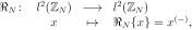
Notice that the DFT is a homomorphism of vector spaces, or equivalently, a linear transformation between the one-dimensional space and itself,
 .
.
This operator has the following properties. Let  and
and  . Then,
1.  .
.
2.  .
.
In addition, the DFT is an injective function because every signal has its own transform, i.e.,  . Because of
  is a finite dimensional space, we can conclude the DFT is a bijective function. The previous theorem shows the DFT is a homomorphism of algebras between
  , the space of one-dimensional signals with the cyclic convolution operation, and
  , the space of one-dimensional signals with the Hadamard product operation. With all of this established, we can now say that:
Theorem 6: The space of one-dimensional signals with the cyclic convolution operation,  , is isomorphic as an algebra for the same space of one-dimensional signals with the Hadamard product
  .
.
Theorem 7: If  then
then
 .
.
4. THE SPACE OF TWO-DIMENSIONAL SIGNALS
The space of two-dimensional signals contains all the functions of the form
 .
.
This space will be denoted by  .
.
A two-dimensional signal  in
in  can be represented as a matrix of size
  ,
,

Also, this space of signals is a vector space over the complex numbers with the sum of functions and the usual product by a scalar number. The standard basis for this space is denoted by

and its elements are defined by

A. The Algebra of Cyclic Convolutions of the order  over
over 
The vector space or signals space  is turned into a linear algebra, which we call a Signal Algebra, by introducing the vector multiplication or signal multiplication operation, denoted by
  where
where  , defined as
 ,
,
where

As in the one-dimensional case, the cyclic convolution operation is commutative in the two-dimensional case, so that we have the following result:
Theorem 8: The space  is a commutative algebra with the cyclic convolution as the multiplication operation.
In the two-dimensional case, there is also a cyclic convolution operator. Indeed, fixing a signal  , we define the cyclic convolution operator as
 .
.
By using the anti-lexicographic order with respect to the standard basis  , the matrix representation of this operator is obtained as
 ,
,
where  . This matrix can be written as the circulant block matrix
 ,
,
where the blocks  are circulant matrices which have the form

and 
B. The Cyclic Correlation
The cyclic correlation operation, denoted by  , over the space of two-dimensional signals
  is defined as

where  is defined by

The cyclic correlation is not commutative but it satisfies the following properties: For every  and
and  we have
1.  .
.
2.  .
.
3.  .
.
Similar to the space of one-dimensional signals, the space of two-dimensional signals is a non-commutative algebra with the operation of the cyclic correlation.
The cyclic correlation operator is defined by fixing a signal 

The matrix representation of this operator, using an anti-lexicographic order with respect to the standard basis, is the following circulant matrix of circulant blocks:
 ,
,
where the blocks  are the circulant matrices
and . 
C. The Hadamard Product
The Hadamard product over the space  is defined by

where  .
.
Fixing a signal  , we define the Hadamard operator as

D. The Reflexive Operator
The reflexive operator over the space of two-dimensional signals is defined by

where

The matrix representation of the cyclic reflexive operator  , using anti-lexicographic order with respect to the canonic basis
  is the circulant matrix of circulant blocks:
 ,
,
where the blocks  are circulant matrices of the form


and  .
.
E. The Cyclic Shifting Operator
The cyclic shifting operator  over the space of two-dimensional signals
  is defined as

where  .
.
The matrix representation of this operator using an anti-lexicographic order with respect to the standard basis  of the space
  is a matrix of circulant blocks with circulant blocks:
 ,
,
where each block  is a circulant matrix of the form
 ,
,
when  and
and  , and
, and
 .
.
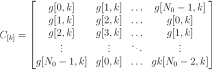
Using an anti-lexicographic order, it is possible to get the matrix-graphical representation of the cyclic convolution operator [4] as is indicated in Figure 1. This representation helps to visualize the matrix of circulant blocks with circulant blocks.

Figure 1. Matrix representation of the cyclic convolution operator
Figure 2. Matrix representation of the cyclic correlation operator
In a similar way, it is possible to get the matrix-graphical representation of the cyclic correlation operator, as is shown in the following figure:
F. Multidimensional Signal Processing
Multidimensional Signal Processing deals with the formulation of theoretical methods for the treatment of multidimensional signals in order to extract important information for a user. The treatment of the multidimensional signals is mostly of an algorithmic nature, which means that the treatment is for creating well-defined procedures for solving a problem in a finite number of steps. A multidimensional signal is any signal which admits a mathematical representation as a numeric function of several independent variables. It is important to distinguish between these signals and a true physical signal, which may be conveying information about multiple observable quantities of physical entities at the same time. For example, a true physical signal may be conveying information about the temperature and pressure of a physical entity. However, this information might not be easily translated into a mathematical formulation. A numeric function of several independent variables can be denoted as  .
.
5. DIGITAL IMAGE PROCESSING
Interest in Digital Image Processing (DIP) methods stems from two principal application areas such as the improvement of pictorial information for human interpretation, and the processing of image data for storage, transmission, and representation for autonomous machine interception [6].
DIP refers to processing digital images by means of a digital computer. A digital image may be defined as a 2-D function  where
where  and
and  are spatial (plane) coordinates, finite and discrete, as well as the amplitude of
  at any pair of coordinates
  , called the intensity or gray level of the image at that point.
A digital image is composed of a finite number of elements, each of which has a particular location and value. These elements are referred to as picture elements, image elements, and pixels.
The number of gray levels typically is an integer power of 2, say  where
where  is the number of bits of quantization. When an image can have
  gray levels, it is common to refer to the image as a "
 -bit image." For example, an image with 256 possible gray-level values is called an 8-bit image.
The information contained in images can be represented in different ways, with the spatial and the frequency representation being the best known. Spatial representation refers to the representation of images as two dimensional (2D) arrays, in which each element of the matrix is called a pixel. For this representation, the matrix notation is commonly used. Figure 3 shows an example of a spatial representation of a very simple image of a unitary impulse. Black pixels are represented by zeros and the white pixels by ones. In the lower left side appears the 3D representation of the unitary impulse. If the image contains  pixels, it is represented by an
  matrix. The representation in the frequency domain of a digital image is obtained by applying the Discrete Fourier Transform (DFT) to the matrix representing the image.

Figure 3. Spatial Representation of Images
Gray scale images were used in this research. In this type of images, intensities of pixels are shades of gray ranging from black to white. This can be viewed clearly in Figure 4. One of the problems confronted is to find the appropriated range of gray values to graphically represent the output from the signal operators, especially if those outputs are negative numbers. Jahne [5] gives an approach to solve this problem as follows: Each pixel in images of 256 gray values occupies 8 bits, which causes negative pixels to take large positive values. "In an 8-bit representation, it is possible to convert unsigned numbers into signed numbers by subtracting 128:
 .
.

Essentially, gray values are regarded in this representation as a deviation from a mean value. In order to have a better display on the screen, the gray values must be converted again to unsigned values by the inverse point operation":  .
.
At this point, we will present a list of the implemented operators in JCID (Java Computational Image Developer). The classification was done according to the functionality of the operators.
1) Point Operators: These operators are used to modify the gray values at specific pixels. They can be applied to correct the image illumination and contrast enhancement: Absolute Value, Clamp, Color Convert.
2) Arithmetic Operators: The basic operations that could be done over images include sum, subtraction, multiplication, and division.
3) Spatial Operators: The function of these operators is to modify the position of the pixels:
. Crop. The operator cuts a portion of the image given the width and height of the section to be cropped.
. Resizing. The operator transforms the image by adding or subtracting pixels.
. Flipping. The operator makes a mirror of the image in a vertical or a horizontal direction.
4) Convolution Operators: These operators are based on the convolution operation of image processing: Sharpening, Blurring, Embossing, and Edge Detection.
5) Filtering Operations: These operators are also based on the convolution operation and are mostly used for image enhancement, highlighting, or hiding features of the image: Low-pass, High-pass, Laplacian, Gaussian, and 2-D Fourier Transform.
6) Complex Operators: These operators have been implemented especially for those images whose pixels are complex numbers: Cyclic Convolution, Cyclic Correlation, Conjugate, Phase, Hadamard Product, and Shifting.
6. WEB-BASED COMPUTATIONAL IMAGE PROCESSING
A. Software Tools used for Implementation
The implementation of all the components of the system was done using the programming language Java. It was chosen because of the following features [6]:
It is object-oriented, which means that the programming of the state and behavior of a system is done by programming the state and behavior of the objects that compound the system.
It is platform-independent, or capable for running on different platforms such as Windows, Linux, or Macintosh.
It is the most common programming language for web applications because it is the foundation of many developing frameworks.
Between the several development projects of the Java community, there are two important API’s specialized for the treatment of images. The first one is the Java Advanced Imaging API, a set of interfaces for manipulating images, and Java Image I/O API which provides the management of image files stored in a local file system or distributed across the network [6]. Considering that it was assumed that the input data are complex signals, meaning that each sample is a complex number (formed by a real number and an imaginary number), an open source library of operations that supports complex numbers was acquired. This library is called Flanagan's Java Library (flanagan.jar), created by Dr. Michael Thomas Flanagan from the University College London. It includes basic arithmetic operations of complex numbers (addition, subtraction, multiplication, and division), trigonometric operations, and special mathematical functions.
For the implementation of the web environment, Java Server Faces, commonly known as JSF, was chosen. JSF is a project from the Java Community Process [7] whose applications are standard Java Web Applications, for which JSF defines three layers: a component architecture which defines a common way to build user interface (UI) widgets, a standard set of UI widgets (such as text boxes, list boxes, tabbed panes, and data grids), and an application infrastructure which uses an HTTP protocol for communication via the Servlet API, it uses JavaServer Pages (JSP) as its display technology, and it uses JavaBeans for exposing properties and event handling [8].
Many distributions of JSF from different companies such as Oracle, IBM, and Apache Project, exist. In this paper, the open source implementation of JSF developed by Apache Project, called MyFaces, was used. Apache Tomcat was used as the servlet container which is used in the "official Reference Implementation for the Java Servlet and JavaServer Pages technologies, providing an environment for Java code to run in cooperation with a web server." Tomcat is cross-platform, running on any operating system that has a Java Runtime Environment.
The JFree Chart is a free Java chart library that makes it easy for developers to display professional quality charts in their applications. This library consists of an API that supports a wide range of chart types, a flexible design that is easy to extend, and targets both server-side and client-side applications. It is distributed under the terms of the GNU Lesser General Public License (LGPL), which permits its use in proprietary applications.
B. Object-Oriented_based Signal Operator Approach
Object-Oriented programming (OOP) is a programming paradigm that uses "objects" to design applications. "An object is a kind of self-sufficient entity that has an internal state (the data it contains) and that can respond to messages (calls to its subroutines). The OOP approach to software engineering is to start by identifying the objects involved in a problem and the messages that those objects should respond to. The program that comes out of it is a collection of objects, each with its own data and its own set of responsibilities. "The objects interact by sending messages to each other" [9]. The Object-Oriented-Based Signal Operator Approach (OOSO) is a methodology used for modeling aspects of the Computational Information Processing (CIP) Framework, which comprises the set of inputs, the set of outputs, and the rules of composition.
1) Data Input Structures: The CSP system has two basic structures of data input. The one-dimensional (1-D) signals of dimension  and the two-dimensional (2-D) signals of dimension
  . A 1-D signal is represented mathematically as a sequence of samples like this:
 .
.
Graphically, this sequence can be seen as a 1-D array, or as a vector data structure:

Figure 5. A 1-D signal represented as vector
A (2-D) signal is represented mathematically as an  matrix. Graphically, this can be seen as a 2-D array data structure, as presented in Figure 6.

Figure 6. A 2-D signal represented as matrix
Making an extension to OOP, both the 1-D and the 2-D signals each represent a class with its own attributes and methods. Figure 7 illustrates the attributes that identify each class.

Figure 7. Class Diagrams of 1-D and 2-D signals
For 1-D signals, the class has been called Signal. The attribute complexSignal of Complex[ ] type is a vector that contains the complex samples read from the data file. If the data are just real numbers, the imaginary part of each sample of the complex array is set to be zero. Each element of the array is an object of the class Complex from Flanagan’s jar library. Figure 8 shows the class diagram of the Complex class. For each loaded signal there is a List of all the transformations resulting from the action of the operators over the signal. This list is represented by the attribute transformedList of the Signal class.

Figure 8. Class Diagrams of the Complex class
The class of 2-D signals has been called ImageJCID. The attribute of RenderedImage type represents the image as a grid of pixels. Images in .jpg, .gif, .bmp, and .tiff formats are easily loaded in this type of data. With this representation, it is possible to obtain the values of the pixels as 2-D arrays, with int data type or as a matrix of complex numbers of type Complex[ ][ ]. As in the 1-D case, each image has its corresponding List of images that come from the action of the operators.
2) Operator Structures: Operators are systems able to transform an input signal to produce an output signal. For the CIP, they were classified in unary operators and binary operators. Unary operators take only one signal on the input and produce one signal on the output. Figure 9 shows an example of a unary operator such as the Discrete Fourier Transform, and an example of a binary operator such as addition.

Figure 9. Example of Unary and Binary Operators
Such a distinction of the unary and binary operators apply to both 1-D signals and 2-D signals. Figure 10 is the class diagram for both kinds of operators. The set of implemented operators is divided into two groups: the OneDimOperators used to transform 1-D signals, and the TwoDimOperators used to transform 2-D signals. Each group is classified as UnaryOperator or BinaryOperator, which in turn, are composed of all the different operators that fit into to each category.

Figure 10. Class Diagrams for Operators
So, the relationship of the transformation of the Operator classes on the Signal classes can be seen in Figure 11.

Figure 11. Class Diagram of the Action of Operators on Signals
C. Web Application Architecture
A web application could be defined as a web system where user input (navigation and data input) affects the state of the logic of the system. The basic architecture of a web application includes browsers, a network, and a web server. In [10] Conallen also states that "a web application uses a web site as the front end to a more typical application." Figure 12 shows the relationship between the main components of a web application.

Figure 12. Components of a Web Application
The connection between the client and server only exists during a page request. Once the request is complete, the connection is broken. All the activity on the server occurs during the page request [10].
The client/server architecture has been one of the most used network architectures to build web applications. In this architecture, the client is the requester of services and the server is the provider of such services. The client could be interpreted as a desktop application installed on several numbers of workstations, which make requests to a single application installed on the server. This kind of interaction is known as two-tiered architecture.
D. Multired Applications
Though many variations are possible, a web application is commonly structured as a three-tiered application, which is the most common example of multi-tier architecture. In its most common form, a web browser is the first tier, an engine created using some dynamic web content technology (e.g., CGI, PHP, Java Servlets, or Active Server Pages) is the middle tier, and a database is the third tier. The web browser sends requests to the middle tier, which services them by making queries and updates on the database and generating a user interface. Figure 13 shows the interaction between the three elements of this architecture.

Figure 13. Three-Tier Architecture
In three-tier applications, the Presentation tier never communicates directly with the Data tier. Additional to this configuration, another component has been added by the Model-View-Controller (MVC) design pattern. This pattern inserts an intermediate component called the controller, which is located between the Presentation tier and the Logic tier. The function of the controller is to process and respond to events, typically user actions, and it invokes changes on the model [11]. Figure 14 illustrates the standard Model-View-Controller Architecture.

Figure 14. Model-View-Controller Architecture
In section 5, it was explained that JavaServer Faces was chosen to implement this architecture for the web-based computational signal processing. This development framework also uses the J2EE (Java Platform, Enterprise Edition) framework of Java Sun Microsystems. "The J2EE platform offers a multi-red distributed application model, reusable components, a unified security model, flexible transaction control, and web services support through integrated data interchange on Extensible Markup Language (XML)-based open standards and protocols" [11]. In the context of the web-based computational signal processing system, the basic structures of the set of multidimensional signals and the set of implemented operators reside in the Model tier of the MVC model. They are invoked by the FacesServeletContext instance of the Controller tier. The next section explains in more detail how each one of the modules that compose the environment was developed.
7. JCID: JAVA COMPUTATIONAL IMAGE DEVELOPER
In order to demonstrate the functionality of the theory presented in section 1, it was necessary to implement an application that could help scientists that work with multidimensional signals [12]. This application was named JCID: Java Computational Image Developer. At first, it was thought that this tool would only process 2-D signals, specifically signals that could be represented as images, but in an advanced stage of the development of the project, the alternative of also processing 1-D signals was considered, since some raw data in this dimension was available to the research group.
This application is part of the general project "WALSAIP: Wide Area Large Scale Automated Information Processing" of the Institute for Computing and Informatics Studies of the Department of Electrical and Computer Engineering. The following research groups participate in this project:
The Advanced Data Management Group (ADMG)
The Automated Information Processing Group (AIPG)
The Human Computer Interfaces Group (HCIG)
The Hydro-Ecological Research Group (HERG)
The Network Communication Infrastructure Group (NCIG)
The Parallel and Distributed Computing Group (PDCG)
The technological infrastructure of this project is composed by a set of 7 servers, each one with 28 disks of 300 Gigabytes, and each research group has at least one of the servers. This infrastructure belongs to the network core of the INEL/ICOM department which acts as an intermediate between the internal network and the exterior world (the Internet and another dependencies of the UPRM). Figure 15 represents a scheme of this infrastructure.

Figure 15. Infrastructure of WALSAIP Project
The WALSAIP project has an agreement with the Jobos Bay Reserve, a dependency of NOAA located in the municipality of Salinas in Puerto Rico, dedicated to the monitoring of the hydrological and ecological factors of the coastal zone. In that reserve some environmental sensors have been set which are collecting information which is being stored in a database. Figure 16 shows a picture of the resources shared by the Jobos Bay Reserve and the UPRM.
The development of the JCID application was done in two phases. In the first phase, a stand-alone version was developed in order to make a "proof of concept" of the implemented operators and the integration in a graphical user interface. The second phase was the implementation as a web application, making use of the network infrastructure described above.
In the design of the application some rules of Usability Engineering and Human Computer Interaction were taken into account in order to provide a user friendly interface that facilitates the work of the scientists. Figure 17 is a screenshot of the graphical user interface of JCID.

Figure 17. Graphical User Interface of JCID
In the menu bar of JCID appear the operators available to process the signals. The operators were classified by the type of functionality, for instance, performing arithmetic operations over the signals. Also, there is a menu of arithmetic operators, like addition, subtraction, multiplication, division, exponential, and logarithmic. If a user is working with an image and wants to enhance it, there is a menu of filtering operators, like edges detection, low pass filter, high pass filter, etc. The user can apply a sequence of operators over the signal, and once an optimal result is obtained, the sequence can be encapsulated in a new operator in order to avoid the repetition of steps in another session which helps the user to make a repository of his/her own operators. Figure 18 illustrates how the sequence of actions is presented to the user.

Figure 18. Encapsulation of Operators
In the right panel of the figure the sequence of operators appears represented as thumbnails of the obtained results. At the end of the sequence, there is a command button to execute the encapsulation of the sequence.
In Figure 19 the dialog windows where the list of operators appears which a user may want to encapsulate, and a small editor can be seen, if the user wants to add more functionalities to the new operator. The operators Dilation and Erosion that appear in the Morphological Operators menu were implemented using the connection between MatLab and Java using the JLab library, described in section 3.2. The operator of the Short Time Fourier Transform (STFT) was also deployed with the Javabuilder toolbox, and it was made by using a trial version of the toolbox.

Figure 19. Edition and Compilation of new Operators
Between other functionalities of JCID, there is an interface to connect to the database that collects the data from the sensors. This interface helps to make queries according to the time interval the user wants to analyze. Results of the queries are stored in files of data and metadata. Data files contain the measurements of the sensors, and metadata files contain the information related to the sensor, its location, and the settings for the sampling of the data. Figure 20 shows a screenshot of the interface.

Figure 20. Connection with the sensors Database
Since it was considered that a user could have data files in other servers o workstations in the network, an open source application was integrated into JCID that allows one to open an FTP connection. This application is called J-FTP, developed by JMethods Inc. Figure 21 is a screenshot of J-FTP.

Figure 21. FTP connection using J-FTP
The web version of JCID has been deployed in the WALSAIP server of the project. It contains the same functionalities that were developed in the stand-alone version. In order to conserve the same graphical configuration of the stand-alone, the user interface of the web version was coded with JavaServer Faces using the tag libraries released in the MyFaces distribution of Apache Project. Figure 22 is a display of the web version.

Figure 22. Graphical User Interface of Web-JCID
8. CONCLUSIONS
This research fits into the development of a computational signal algebra framework for modeling, simulation, and processing applications using digital images. The Computational Signal Processing Environment has been designed to be a useful tool for geologists, hydrologists, and scientists in related areas. It provides a friendly access to basic and advance operators, with encapsulation capabilities. One of the most important features of the environment is the portability offered by Java implementation, which also facilitates the availability of deploying the source code for potential users and developers. Finally, the integration of Java with scripting languages like MatLab diminishes the time consumed in coding and provides a better tool for scientists who do not have experience in programming languages.
REFERENCES
[1] DAVIS, P. J., Circulant Matrices, John Wiley and Sons, 1979.
[2] MITRA, S. K., Digital Signal Processing: A Computer-Based Approach, Mc Graw Hill, 2001.
[3] PAREDES, M., RODRÍGUEZ, D. and VILLAMIZAR, J., La estructura algebraica del espacio de señales unidimensionales, Revista Integración, vol. 23, pp. 15-39, 2005.
[4] VILLAMIZAR, J., A Computational Signal Algebra Framework for Image Interferometry Processing Applications, Master Thesis, Electrical and Computer Engineering Department; University of Puerto Rico at Mayaguez, 2006.
[5] JÄHNE B., Digital Image Processing, Springer, 2005.
[6] Java Technology, http://www.sun.com
[7] Java community process, http://jcp.org/en/home/index.html
[8] MANN K. D., JavaServer Faces in Action, Manning Publications Co., 2005, pp. 16-37.
[9] ECK D. J., Introduction to programming using java, Hobart and William Smith Colleges, http://math.hws.edu/javanotes, 2006.
[10] CONALLEN J., Modeling Web application architectures with UML, Communications of the ACM, vol. 42, no. 10, pp. 63-70, 1999.
[11] BODOFF, S., ARMSTRONG, E., BALL, J., BODE, D., EVANS I., GREEN, D., HAASE, K. and JENDROCK, E. The J2EE Tutorial, Addison Wesley, 2004, pp. 2-10.
[12] BAUTISTA, L. X., Web-based Data Processing for Environmental Surveillance Monitoring Applications, Master Thesis, Electrical and Computer Engineering Department, University of Puerto Rico at Mayaguez, 2007.
Cómo citar
IEEE
ACM
ACS
APA
ABNT
Chicago
Harvard
MLA
Turabian
Vancouver
Descargar cita
Visitas a la página del resumen del artículo
Descargas
Licencia
Derechos de autor 2011 DYNA

Esta obra está bajo una licencia internacional Creative Commons Atribución-NoComercial-SinDerivadas 4.0.
El autor o autores de un artículo aceptado para publicación en cualquiera de las revistas editadas por la facultad de Minas cederán la totalidad de los derechos patrimoniales a la Universidad Nacional de Colombia de manera gratuita, dentro de los cuáles se incluyen: el derecho a editar, publicar, reproducir y distribuir tanto en medios impresos como digitales, además de incluir en artículo en índices internacionales y/o bases de datos, de igual manera, se faculta a la editorial para utilizar las imágenes, tablas y/o cualquier material gráfico presentado en el artículo para el diseño de carátulas o posters de la misma revista.