Structural control using magnetorheological dampers governed by predictive and dynamic inverse models
DOI:
https://doi.org/10.15446/dyna.v81n188.41774Palabras clave:
Dynamics of structures, semi-active control of structures, inverse models, predictive models, neural networks, magnetorheological dampers. (es)Descargas
https://doi.org/10.15446/dyna.v81n188.41774
Structural control using magnetorheological dampers governed by predictive and dynamic inverse models
Control estructural utilizando amortiguadores magnetoreológicos gobernados por un modelo predictivo y por un modelo inverso dinámico
Luis Augusto Lara-Valencia a, José Luis Vital-de Brito b & Yamile Valencia-Gonzalez c
a Universidad Nacional de Colombia, Medellín, Colombia.
lualarava@unal.edu.co
b University of Brasilia, Brasilia, Brazil. jlbrito@unb.br
c Universidad Nacional de Colombia, Medellín, Colombia.
yvalenc0@unal.edu.co
Received: January 27th, 2014. Received in revised form: July 2th, 2014. Accepted: July 24th, 2014.
Abstract
The present paper implements a novelty
semi-active structural control design on a two-story building, with the aim of
reducing vibrations caused by transient type loads. The analyzed structure
corresponds to an experimental prototype that was fully characterized and
modeled according to the diaphragm hypothesis. The controller used was based on
the action of a pair of real magnetorheological (MR) dampers whose operation is
emulated by the phenomenological model. These mechanisms are governed by a
numerical system that is based on non-linear autoregressive model with
exogenous inputs (NARX)-type artificial neural networks, which have the ability
to determine the necessary optimal control forces and the voltages required for
the development of these forces through a prediction model and an inverse
model, which are pioneers in this kind of systems. The results obtained show
that the control design based on neural networks that was developed in the
present study is a reliable and efficient, achieving reductions of up to 69%
for the peak response value.
Keywords: Dynamics of structures, semi-active control of structures, inverse models, predictive models, neural networks, magnetorheological dampers.
Resumen
En este
artículo se implementa um novedoso proyecto de control estructural numérico en
una edificación de dos pisos con el objetivo de reducir vibraciones debidas a
cargas de tipo transiente. La estructura analizada corresponde a un prototipo
experimental debidamente caracterizado y modelado de acuerdo con la hipótesis
del diafragma. El controlador utilizado se basa en la acción de un par de
amortiguadores magnetoreológicos (MR) reales cuyo funcionamiento es emulado a
través del denominado modelo fenomenológico. Los disipadores son gobernados por
un sistema numérico basado en redes neuronales artificiales del tipo NARX con
la capacidad de determinar fuerzas óptimas de control y voltajes a través de un
modelo de predicción y un modelo inverso, los cuales son de uso inédito en este
tipo de sistemas. Los resultados obtenidos muestran que el proyecto de control
basado en redes neuronales desarrollado en este trabajo es un controlador
confiable y eficiente, consiguiendo reducciones de hasta 69% en los valores
pico de respuesta.
Palabras Clave: Dinámica de estructuras, control semi-activo de estructuras, modelos inversos, modelos predictivos, redes neuronales, amortiguadores magnetoreológicos.
1. Introduction
The proposed control algorithm calculates the optimal control force required by the MR dampers to reduce the movement of the protected structure. However, the algorithm must also determine the voltage required for the controller because the increases or decreases in the forces produced by the damper are indirectly controlled by the voltages applied to the device.
In this work, the capacity and efficiency of the control design that has been proposed for a building was evaluated. Thus, a numerical model was built for a 2-story gantry, where 2 MR dampers were installed and controlled by the developed control algorithm. The structure was subjected to acceleration at the base, and the response values of the system both with and without control were calculated to evaluate the operation of the control strategy presented.
2. Studied Model
The model studied in the present paper consisted of a 2-story gantry, analyzed in 3 dimensions, with 3 degrees of freedom per floor (horizontal displacements in the X and Y axes and rotation around the Z axis). In addition, the model considered the use of a pair of MR dampers installed at the height of the first floor of the building that control the system. The model was a 2:3 scale experimental prototype built at the Laboratory of the Department of Structures, Geotechnics and Applied Geology of the University of Basilicata in Italy that was used in a joint research project between the Italian Seismic Engineering University Laboratories Network (Rede de Laboratórios Universitários Italianos de Engenharia Sísmica - ReLUIS) and the Italian Civil Protection Department (Departamento de Proteção Civil Italiano - DPC).
2.1. Parameters and properties of the building
The 2-story gantry was 2 m tall between the floors, and the building was a rectangle with a distance of 3 m between the axes of the pillars in the Y direction and 4 m in the X direction. The gantry modeling was conducted in 3 dimensions, adopting the diaphragm hypothesis that assumes that each slab is rigid in its own plane and flexible in the perpendicular direction. It was also established that the horizontal displacements of all floor nodes were related to 3 rigid body displacements that were defined in the center of mass of each floor, i: uxi translations in the x direction, uyi in the y direction, and uqi torsion rotation around the z vertical axis. Fig. 1 shows a photograph of the actual model, located at the University of Basilicata in Italy, taken by [1].
The mass, stiffness and damping matrix of the analyzed building can be consulted in [2]
2.2. Parameters and properties of the MR dampers
The devices used to control the structure were a pair of compact RD-1005-3 MR dampers, manufactured by the Lord Corporation in Cary, NC, USA. To numerically simulate the behavior of these devices, the phenomenological model proposed in [3], was used.
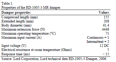
Table 1 shows the primary properties of RD-1005-3 MR dampers, according to the technical specifications published by the manufacturer [4].
In [5] the parameters that characterize the behavior of the RD-1005-3 MR damper are identified. Was found that some of these parameters remained constant under varying operating conditions; thus, for example, fixed values of k0, n, and k1(x-x0) were defined based on tests seeking to determine the mechanical characteristics of the damper, while others, such as the A, b, and g values, were constant values suggested in the literature [3]. The damper parameters that were assumed to be constant values are listed in Table 2.
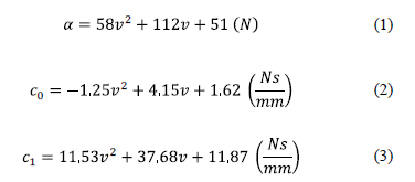
However, was identified that the parameters a, c0, and c1 of the RD-1005-3 MR damper to be voltage-dependent parameters [5]. The equations that describe these relationships are the following:
3. Controller based on a predictive model and an inverse dynamic model developed through NARX-Type artificial neural networks
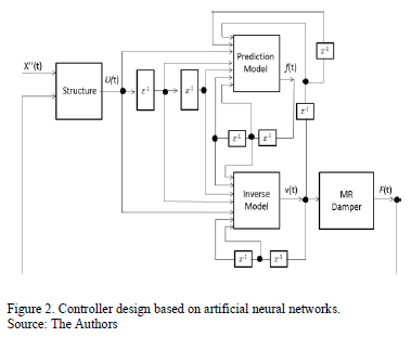
The primary purpose of the control algorithm based on ANNs herein presented is to define a model capable of calculating the optimal control force to be applied by the energy dissipation mechanism such that it reduces the movement of the protected structure as much as possible. However, the control design must also focus on determining the voltage to be applied to the controller because the increase or decrease of forces produced by MR dampers is indirectly controlled through the voltage applied to the device. To determine these two fundamental parameters, the optimal force and voltage, two properly trained NARX networks were used. The first network simulates a prediction model tasked with determining the optimal control force required for the MR to minimize the vibrations of the structure in the most efficient manner possible when it is subjected to external forces on its base. The second network works as an inverse model, i.e., the network determines the input of the control design based on the delayed outputs of the system. Thus, the second network is occupied with defining the proper voltage to be applied to the control device such that it will apply a force to the structure close to the optimal force, which was calculated by the first neural network.
Fig. 2 presents a diagram of the control based on the ANN developed to reduce the vibrations of the analyzed structure.
3.1. Prediction model of the optimal control force
The proposed prediction model of the optimal force is formed by a NARX-type neural network that is completely interconnected and configured with a layer of sensory units composed of fifteen input signals and one bias term, a computational processing layer consisting of sixteen hidden neurons, and a layer of results formed by a single output. A diagram of the network used in the prediction model of the force is shown in Fig. 3.
The selection of the number of layers and components per layer for each of the neural networks developed does not follow a specific procedure; it varies from application to application and is essentially a trial-and-error exercise. In general, the use of a hidden layer is adequate to model highly complex functional dependencies. This ability was demonstrated in our early experiences, where we attempted to reproduce the operation of the proposed NARX networks (predictive and inverse model). When the networks were modeled with two or more hidden layers, the results obtained from the processors were virtually identical to the results achieved by the networks whose computational units were distributed in a single hidden layer. Moreover, the computational efficiency of the networks that had a hidden layer was remarkably greater, which supports the choice of the number of network layers necessary for optimal performance.
The choice of the number of neurons in the hidden layers was decided through a survey process. NARX networks were analyzed with a hidden layer and various amounts of neurons (ranging from 8 to 30 neurons). Each of these networks was evaluated according to two specific parameters, processing time and performance (measured from the mean square error of the training process), ranging from 0 to 1. The value of 1 was given to the network with the best performance among all the networks, and the value 0 was represented the network with the poorest performance within the analyzed group of networks. The networks in between the extremes received a weighting between these two values based on the estimation of the equivalent percentage of the evaluated parameters compared with the best performance parameter values. The result of the process showed that the ideal number of neurons for a hidden layer in the NARX networks should be equal to 16.
Finally, the inputs of the neural networks were determined based on the work of He and Asada [6]. In this work, it was shown that a second-order input model was adequate to identify the characteristics of an MR damper, and based on this finding, it was decided to use delays in the inputs of the processors of one and two units of time, as shown in Fig. 3.
The hyperbolic tangent sigmoid function and piecewise linear function were used for activating the neurons in the hidden and ouput layers respectively; the Levenberg-Marquadt algorithm was used for training the synaptic conections of the artificial neural network.
3.2. Inverse model applied to determine the voltage of the control device
The inverse model proposed to determine the voltage to be applied to the MR damper consists of a fully interconnected NARX network. Similarly to the prediction model, the network is configured with an input layer composed of fifteen input signals, a hidden layer with sixteen neurons, and a output layer with a single output. This neural network uses the hyperbolic tangent sigmoid function and piecewise linear function for activating the neurons in the hidden and ouput layers respectively.
The input layer of the neural network that composes the inverse model is formed by the displacement, speed, and acceleration values of the structure, the optimal control force values calculated in the prediction model, and the feedback inherent to the recurrent network with the output value (voltage). The choice of order of the network delay lines was again based on the results obtained by [6]. Fig. 4 shows the neural network model used in the inverse model.
4. Conditioning of both the predictive model and the inverse model used in the control design
As previously mentioned, the control design was based on a predictive model and an inverse model acting together. The predictive model determined the optimal control force values, while the inverse model defined the voltage values applied in the damper. Both models were run based on NARX-type neural networks.
Because the use of neural networks leads to a series of conditioning tasks (training and validation), the detailed procedure used by [7] to condition the prediction models used in the present study is presented below.
4.1. Conditioning the prediction model for the optimal control force
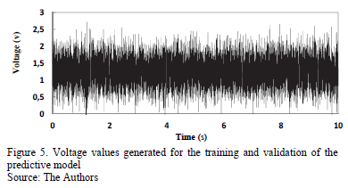
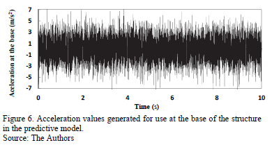
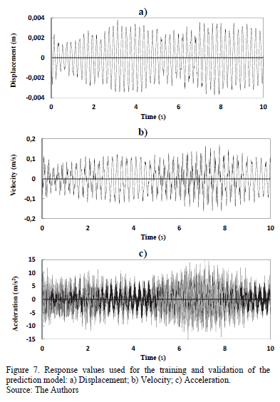
The dataset used for the training and subsequent validation of the neural network designed for the predictive model was generated by 2 normally distributed series of random numbers for 2 specific parameters: acceleration and voltage. The acceleration values generated in the random series were applied at the base of the structure and were discretized in the numerical model. These acceleration values were produced according to the ordering in time and magnitude of the possible model responses. For such purposes, the sampling frequency of the acceleration parameter was 1 x 10⁻³ s, and the amplitude values ranged approximately within the interval [-6, 6] m/s2. The application of random acceleration on the base of the structure works as a type of filter, with the obtained responses (displacement, velocity, and acceleration values) in the state representation of the analyzed building creating consistent values to feed the network. Thus, the input dataset for the training processes and the validation of the prediction model were as follows: the responses obtained fro. m the structure (displacement, velocity, and acceleration); the voltage values generated from a series of normally distributed data, with a sampling frequency of 1 x 10⁻³ s and an amplitude of 2.5 v; and the optimal control force values generated in the neural network output, which enters the system through the use of a delay line to produce system feedback.
Figs. 5 and 6, respectively, present the voltage and acceleration values over time, generated based on the series of normally distributed random data.
With the excitation of the structure defined, the response values could then be obtained from the modeled gantry. These values, along with the voltage values shown in Fig. 5 and the optimal force values determined by the model, comprised the set of sensory units that constituted the input layer of the prediction model. Fig. 7 shows the response values obtained by applying the excitation, shown in Fig. 6, to the structure.
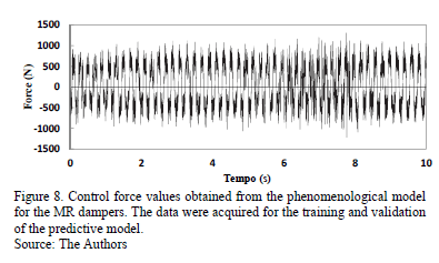
The network training and validation dataset was complemented with the definition of the target output values for the system. For the specific case of the prediction model, the desired outputs were the control force values obtained from the phenomenological model of the MR dampers. The mechanical model depended on the voltage values and the structure responses. Thus, working with the parameters shown in Figs. 5 and 7 in the model proposed in [3], the control force values were obtained according to the input parameters of the established neural network. Fig. 8 shows the desired control force values (target output) that were originated by the phenomenological model of the MR dampers as a result of the introduction of the responses and voltages specified in the input layer of the network.
4.2. Conditioning of the applied inverse model to determine the voltage values for the control device
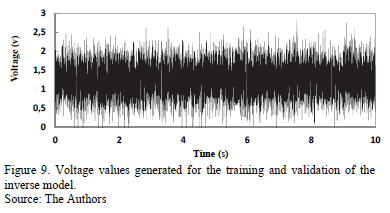
The data used for the training and validation of the network that composed the inverse model were developed based on 2 random series of numbers generated from a normal distribution. In the specific case of the inverse model, the random parameters that generated the input values for the system were the output of the NARX network (voltage) and an acceleration value that was applied at the base of the studied gantry. The response values of the structure were the result of the application of the random acceleration to the gantry and were determined from the state representation of the system, and the control force values were the result of the insertion of the voltage values and structure responses into the mechanical model of the MR dampers. The sampling frequency values of the generated voltage and acceleration were both 1 x 10⁻³s, while the amplitudes of the generated parameters were approximately 2.5 V e ± 6 m/s2. Fig. 9 and 10 show the variation, over time, of the randomly generated voltage and acceleration values, respectively, that enabled the training and validation of the network proposed in the inverse model.
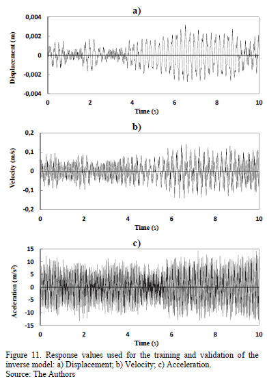
The displacement, velocity, and acceleration values of the structure, which were obtained from the application of the acceleration values shown in Fig. 10, are presented in Fig. 11. These variables were the response values of the input layer used in the training and validation of the neural network that comprises the inverse model.
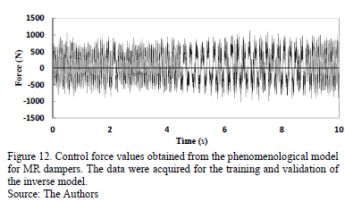
Finally, the control force values obtained from the phenomenological model of the device, which also served as source nodes in the sensory unit of the inverse model, are shown in Fig. 12. Although the control force values for the training and validation of the system were dependent on the response and voltage values of the analyzed model, these values were part of the system input, generating output values that correspond to the input values from the control plant.
5. Performance of the proposed control model
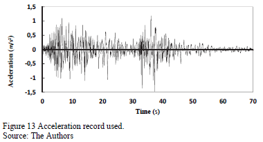
The proposed control model was tested on the studied gantry. The base of the structure was subjected to the excitation action shown in Fig. 13. The acceleration record that was used to excite the structure was scaled in time and magnitude to make it compatible with the structure dimensions.
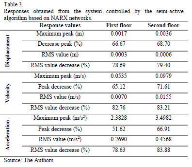
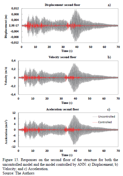
For the specific case of a decrease in the displacement peaks of each floor of the structure, the values obtained when control was managed by neural networks were 66.67% for the first floor and 68.70% for the second floor when compared with the displacement peaks of the uncontrolled structure, which correlates to peak response values of 0.0017 m and 0.0036 m for the first and second floors, respectively. When a comparative exercise was performed using the RMS (Root-Mean-Square) values of the displacement, decreases in the displacement values of 78.69% and 79.40% were observed for the first and second floors of the structure.
Table 3 shows the response values of the structure when managed by the control design proposed in the present study. The decreases in the values of these responses were calculated when compared with the values obtained in the uncontrolled structure.
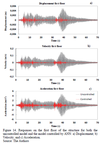
Figs. 14 and 15 shows the variation in the responses of the structure over time. The cases shown correspond to the model controlled by the NARX neural networks and to the model where no control is exerted.
The behavior of the prediction model for the generated controller can be observed in Fig. 16. In this graph, it is possible to observe how the selected voltage values vary over time according to the system requirements. The initial voltage value for the MR dampers is 1.5 volts; therefore, the network started with this voltage value to determine in which direction the voltage value would generate control force values that approached the desired control force values obtained from the prediction model. As observed, the voltage in this case never reached 0; this result is primarily due to the nature of the excitation, which, during the time of the analysis, never ceased to influence the structure. Considering that this influence was small in the last 10 s, it should be noted that the proposed neural networks were designed with 2 delay lines, which means that the neural
networks made decisions based on up to 2 instants of past time; therefore, when the structure responses became stable, the system entered into a repetition of output values, resulting in a virtually fixed voltage value or, in this specific case, a voltage value with little variation at the end of the observation period.
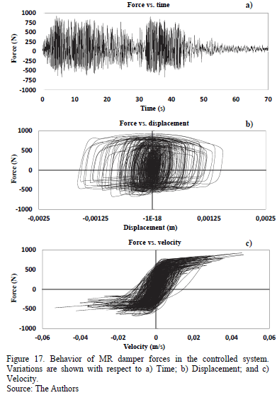
In addition, Fig. 17 shows the variation in the control force values of the system caused by the voltage value variations generated in the prediction model of the controller. The control force values were examined with respect to time, displacement, and velocity.
6. Conclusions
A semi-active control design was developed in the present article using MR dampers that were managed by a control algorithm based on artificial neural networks. To measure the functionality and performance of the proposed system, a numerical application was developed using the control design on a 3-dimensional, 2-story structure that was subjected to the actions of a transient load.
The controller that was developed based on neural networks was able to reduce the peak and the RMS response values for the displacement of the structure by 67% and 79%, respectively, on average. For velocity, the peak and RMS response values were decreased by approximately 69% and 83%, respectively. Finally, for acceleration, an average reduction of 57% and 81% was achieved for the peak and response RMS values, respectively.
Based on the obtained numerical results, the control design based on neural networks that was developed in the present study can be considered an efficient, robust, reliable, and constant controller that was able to reduce the response values of the analyzed model. To accomplish this, the predictive and inverse models acted in a competent, appropriate, and synchronized manner, despite the complexity of the problem and solution. Perhaps the greatest weakness for this control alternative was the demand for processing time, which hindered its execution in real time and would raise the cost of project implementation due to the need for elements with high computing power to solve the problem more quickly.
Acknowledgements
The authors acknowledge the support provided by the University of Brasília (Universidade de Brasília), the National University of Colombia, Medellin campus (Universidad Nacional de Colombia, sede Medellín), and the National Council for Scientific and Technological Development (Conselho Nacional de Desenvolvimento Científico e Tecnológico - CNPq) for the development of the present study.
References
[1] Carneiro, R., Controle semi-ativo de vibrações em estruturas utilizando amortecedor magnetorreológico PhD. Thesis, Doutorado em Estruturas e Construção Civil, Universidade de Brasília, Distrito Federal, Brasilia, Brasil, 2009, 135 P.
[2] Lara, L., Brito, J. y Valencia, Y. Reducción de vibraciones en un edificio mediante la utilización de amortiguadores magnetoreológicos. DYNA, 79 (171), pp. 205-214, 2012.
[3] Spencer Jr., B.F., Dyke, S.J., Sain, M.K. and Carlson, J.D., Phenomenological model of a magnetorheological damper. Journal of engineering mechanics, 123 (3), pp. 230-238, 1997. https://doi.org/10.1061/(ASCE)0733-9399(1997)123:3(230)
[4] Lord Corporation, Lord technical data RD-1005-3 Damper, Technical data, Lord Corporation, Cary, North Carolina, 2006.
[5] Basili, M., Controllo semi attivo di strutture adiacenti mediante dispositivi magnetoreologici: Teoria, sperimentazione e modellazione PhD. Thesis, in Structural Engineering, Università degli studi di Roma "La Sapienza", Roma, Italia, 2006.
[6] He, X. and Asada, H., A new method for identifying orders of input-output models for nonlinear dynamic systems, Proceedings of the American Control Conference, San Francisco, California, USA, pp. 2520-2523, 1993.
[7] Lara, L.A., Estudo de algoritmos de controle semi-ativo aplicados a amortecedores magnetorréologicos, PhD. Thesis, Doutorado em Estruturas e Construção Civil,: Universidade de Brasília, Distrito Federal, Brasilia, Brasil, 2011, 223 P.
L.A. Lara-Valencia, received the BSc. in Civil Engineering in 2005 from Universidad Nacional de Colombia, campus Medellin, Colombia; the MSc. and Dr. degrees in Structures and Civil Construction in 2007 and 2011, respectively from the University of Brasilia, Brazil. Currently he is a full professor in the Civil Engineering department of the Universidad Nacional de Colombia, campus Medellin, Colombia. His research interest includes: vibration control of structures, dynamics of structures, linear and nonlinear finite elements modeling, foundations and tropical soils.
J.L. Vital-de Brito, received the BSc. in Civil Engineering in 1974 from University Estadual Paulista, Brasil the MSc. and Dr. degrees in Civil Engineering in 1979 and 1995, respectively from the University Federal do Rio Grande do Sul, Brasil. Currently he is a full professor in the Civil and Environmental Engineering department of the University of Brasilia and an active reviewer from the Journal of the Brazilian Society of Mechanical Sciences and Engineering. His research interest includes: dynamic of structures, structural stability, aerodynamics and vibration control.
Y. Valencia-Gonzalez, received the BSc. in Civil Engineering in 2001, the MSc. degree in Civil Engineering-Geotechnical in 2005, both from Universidad Nacional de Colombia, campus Medellin, Colombia. In 2009 received the Dr. degree in Geotechnical Follow by a year as postdoctoral fellow, all of them in the University of Brasilia, Brasil. Currently she is a full professor in the Civil Engineering department of the Universidad Nacional de Colombia campus Medellin, Colombia. Her research interest includes: tropical soils, biotechnology, foundations and vibration control.
Cómo citar
IEEE
ACM
ACS
APA
ABNT
Chicago
Harvard
MLA
Turabian
Vancouver
Descargar cita
Licencia
Derechos de autor 2014 DYNA

Esta obra está bajo una licencia internacional Creative Commons Atribución-NoComercial-SinDerivadas 4.0.
El autor o autores de un artículo aceptado para publicación en cualquiera de las revistas editadas por la facultad de Minas cederán la totalidad de los derechos patrimoniales a la Universidad Nacional de Colombia de manera gratuita, dentro de los cuáles se incluyen: el derecho a editar, publicar, reproducir y distribuir tanto en medios impresos como digitales, además de incluir en artículo en índices internacionales y/o bases de datos, de igual manera, se faculta a la editorial para utilizar las imágenes, tablas y/o cualquier material gráfico presentado en el artículo para el diseño de carátulas o posters de la misma revista.


