DISEÑO DE ZAPATAS COMBINADAS DE LINDERO DE FORMA RECTANGULAR UTILIZANDO UN NUEVO MODELO
Design of boundary combined footings of rectangular shape using a new model
DOI:
https://doi.org/10.15446/dyna.v81n188.41800Palabras clave:
boundary combined footings, resultant force, center of gravity, bending moment, bending shear, punching shear. (es)Combined footing of boundary, Resultant force, Center of gravity, Bending moment, Shear force by bending, Shear force by penetration (en)
Descargas
Este documento presenta el diseño de zapatas combinadas de lindero de forma rectangular utilizando un nuevo modelo para considerar las presiones reales del suelo que actúan en la superficie de contacto de la zapata, dichas presiones se presentan en función de una carga axial, momento alrededor del eje “X” y momento alrededor del eje “Y” de cada columna. El modelo clásico considera una carga axial y un solo momento alrededor del eje “X” (eje transversal) aplicada en cada columna, es decir, la fuerza resultante de las cargas aplicadas se localiza sobre el eje “Y” (eje longitudinal). La parte principal de esta investigación es que el modelo propuesto considera momentos flexionantes alrededor del eje “Y” y el modelo clásico no los toma en cuenta. Entonces el nuevo modelo es el más apropiado, ya que se apega más a las condiciones reales y es más económico.
This paper presents the design of boundary combined footings of rectangular shape using a new model to consider real soil pressure acting on the contact surface of the footing; such pressure is presented in terms of an axial load, moment around the “X” axis and moment around the “Y” axis to each column. The classic model considers an axial load and moment around the transverse axis applied in each column, and when the moments in two directions are taken into account, the maximum pressure throughout the contact surface of the footing is considered the same. The main part of this research is that the proposed model considers real soil pressure and the classic model takes into account the maximum pressure and uniform is considered. It is concluded that the proposed model is more suited to the real conditions and is more economical.
https://doi.org/10.15446/dyna.v81n188.41800
Design of boundary combined footings of rectangular shape using a new model
Diseño de zapatas combinadas de lindero de forma rectangular utilizando un nuevo modelo
Arnulfo Luévanos-Rojas
University of Durango State, Gómez Palacio, Durango, México. arnulfol_2007@hotmail.com
Received: January 28th, 2014. Received in revised form: August 6th, 2014. Accepted: August 11th, 2014.
Abstract
This paper presents the design of boundary combined footings of rectangular shape using a new model to consider real soil pressure acting on the contact surface of the footing; such pressure is presented in terms of an axial load, moment around the "X" axis and moment around the "Y" axis to each column. The classic model considers an axial load and moment around the transverse axis applied in each column, and when the moments in two directions are taken into account, the maximum pressure throughout the contact surface of the footing is considered the same. The main part of this research is that the proposed model considers real soil pressure and the classic model takes into account the maximum pressure and uniform is considered. It is concluded that the proposed model is more suited to the real conditions and is more economical.
Keywords: boundary combined footings; resultant force; center of gravity; bending moment; bending shear; punching shear.
Resumen
Este
documento presenta el diseño de zapatas combinadas de lindero de forma
rectangular utilizando un nuevo modelo para considerar la presión real del
suelo que actúan en la superficie de contacto de la zapata, dicha presión se
presenta en función de una carga axial, momento alrededor del eje "X" y momento
alrededor del eje "Y" de cada columna. El modelo clásico considera una carga
axial y un momento alrededor del eje transversal aplicada en cada columna, y
cuando los momentos en dos direcciones son tomados en cuenta, la presión máxima
en toda la superficie de contacto de la zapata se considera la misma. La parte
principal de esta investigación es que el modelo propuesto considera la presión
real del suelo y el modelo clásico toma en cuenta la presión máxima y la
considera uniforme. Se concluye que el
nuevo modelo es el más apropiado, ya que se apega más a las condiciones
reales y es más económico.
Palabras clave: zapatas combinadas de lindero; Fuerza resultante; Centro de gravedad; Momento flexionante; Fuerza cortante por flexión; Fuerza cortante por penetración.
1. Introduction
The foundation is the part of the structure which transmits the loads to the soil. Each building demands the need to solve a problem of foundation. The foundations are classified into superficial and deep, which have important differences: in terms of geometry, the behavior of the soil, its structural functionality and its constructive systems [1,2].
Superficial foundations may be of various types according to their function; isolated footing, combined footing, strip footing, or mat foundation [1-4].
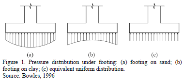
The distribution of soil pressure under a footing is a function of the type of soil, the relative rigidity of the soil and the footing, and the depth of foundation at level of contact between footing and soil. A concrete footing on sand will have a pressure distribution similar to Fig. 1(a). When a rigid footing is resting on sandy soil, the sand near the edges of the footing tends to displace laterally when the footing is loaded. This tends to decrease in soil pressure near the edges, whereas soil away from the edges of footing is relatively confined. On the other hand, the pressure distribution under a footing on clay is similar to Fig. 1(b). As the footing is loaded, the soil under the footing deflects in a bowl-shaped depression, relieving the pressure under the middle of the footing. For design purposes, it is common to assume the soil pressures are linearly distributed.
The pressure distribution will be uniform if the centroid of the footing coincides with the resultant of the applied loads, as shown in Fig. 1(c) [1].
In the design of superficial foundations, in the specific case of isolated footings, there are of three types in terms of the application of loads: 1) The footings subjected to concentric axial load, 2) The footings subjected to axial load and moment in one direction (unidirectional bending), 3) The footings subjected to axial load and moment in two directions (bidirectional bending) [1,2,5,6].
The hypothesis used in the classical model considers the axial load and moment around an axis transverse to the combined footing for the geometric proportions and shape are so fixed that the centroid of the footing area coincides with the resultant of the column loads. This results in uniform pressure below all the contact area of the footing. Then the equation of the bidirectional bending is used to obtain the stresses acting on the contact surface of the combined footings, which must meet the following conditions: 1) The minimum stress should be equal to or greater than zero, because the soil is not capable of withstand tensile stresses, 2) The maximum stress must be equal or less than the allowable capacity that can withstand the soil [1,2,5,6].
A combined footing is a long footing supporting two or more columns in (typically two) one row. The combined footing may be rectangular, trapezoidal or Tee-shaped in plan. Rectangular footing is provided when one of the projections of the footing is restricted or the width of the footing is restricted. Trapezoidal footing is provided when one column load is much more than the other. As a result, both projections of the footing beyond the faces of the columns will be restricted [7-9].
Some papers present the use of load testing on foundations: Non-destructive load test in pilots [10]; Evaluation of the integrity of deep foundations: analysis and in situ verification [11]; Other, shows the use of static load tests in the geotechnical design of foundations [12]; Comparison between resonant-column and bender element test on three types of soils [13].
Mathematical models have been developed to obtain the dimensions of rectangular, square and circular isolated footings subjected to axial load and moments in two directions (bidirectional bending) [14-16]. Also, a mathematical model was presented for design of isolated footings of rectangular shape using a new model [17].
This paper presents a full mathematical model for the design of boundary combined footings to obtain: 1) Moments around of an axis a1'-a1' with a width "b1" and a2'-a2' with a width "b2" that are parallel to axis "Y-Y", and moments around of an axis b'-b', c'-c', d'-d' and e'-e' that are parallel to axis "X-X"; 2) Bending shear; 3) Punching shear for footings which support a boundary column and other inner column subject to axial load and moment in two directions (bidirectional bending), where pressures are different in the four corners, these pressures are presented in terms of the mechanical elements (axial load, moment around the axis "X-X" and moment around the axis "Y-Y").
2. Methodology
2.2. General conditionsAccording to Building Code Requirements for Structural Concrete (ACI 318-13) and Commentary the critical sections are: 1) the maximum moment is located in face of column, pedestal, or wall, for footings supporting a concrete column, pedestal, or wall; 2) bending shear is presented at a distance "d" (distance from extreme compression fiber to centroid of longitudinal tension reinforcement) shall be measured from face of column, pedestal, or wall, for footings supporting a column, pedestal, or wall; 3) punching shear is localized so that its perimeter "bo" is a minimum but need not approach closer than "d/2" to: (a) Edges or corners of columns, concentrated loads, or reaction areas; and (b) Changes in slab thickness such as edges of capitals, drop panels, or shear caps [18].
The general equation for any type of footings subjected to bidirectional bending [14-17, 19-21]:

where: s is the stress exerted by the soil on the footing (soil pressure), A is the contact area of the footing, P is the axial load applied at the center of gravity of the footing, Mx is the moment around the axis "X", My is the moment around the axis "Y", Cx is the distance in the direction "X" measured from the axis "Y" up to the farthest end, Cy is the distance in direction "Y" measured from the axis "X" up to the farthest end, Iy is the moment ofinertia around the axis "Y" and Ix is the moment of inertia around the axis "X".
2.2. New model
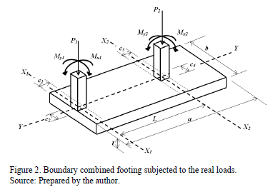
Fig. 2 shows a combined footing supporting two rectangular columns of different dimensions (a boundary column and other inner column) subject to axial load and moments in two directions in each column.
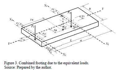
Fig. 3 presents a combined footing due to the equivalent loads. The mechanical elements of the components P1, Mx1, My1 are equivalent to a normal force "P1" acting on the point with coordinates (ex1, ey1), and for the components of P2, Mx2, My2 are equivalent to a normal force "P2" acting on the point with coordinates (ex2, ey2).
The general equation of the bidirectional bending is:

where: sadmis the capacity of available allowable load of the soil, R is the resultant force of the forces, yc is the distance from the center of the contact area of the footing in the direction "Y" to the resultant, xc is the distance from the center of the contact area of the footing in the direction "X" to the resultant.
Now the sum of moments around the axis "X1" is obtained to find "yR" and the resultant force is made to coincide with the gravity center of the area of the footing with the position of the resultant force in the direction "Y", therefore there is not moment around the axis "X" and the value of "yc" is zero, "xR = xc" is the sum of moments around the axis "Y" divided by the resultant, which is:

Substituting equation (3) into equation (2) is transformed into a unidirectional bending system as follows:

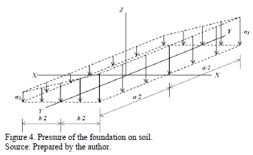
Fig. 4 shows pressure diagram for combined footings subject to axial load and moment in one direction (unidirectional bending) in each column, where the pressures are presented at two different corners varying linearly along the contact surface, because there is not moment around the axis "X".
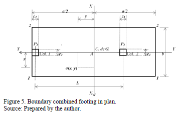
Fig. 5 presents a boundary combined footing to obtain the stresses anywhere of the contact surface of the structural member due to the pressure that is exerted by the soil.
- In the longitudinal direction:

- In the transverse direction:
v To the boundary column is:

v To the intermediate column is:

where: b1 = c1+d/2 is the width of the failure surface, b2 = c3+d.
2.2.1. Model to obtain the bending moments
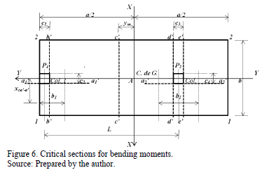
Critical sections for bending moments are shown in Fig. 6, these are presented in sections a1'-a1', a2'-a2', b'-b', c'-c', d'-d' and e'-e'.
2.2.1.1. Moment around the axis a1'-a1'
The resultant force "FRa1'" is found through the volume of pressure the area formed by the axis a1'-a1' with a width "b1 = c1+d/2" and the free end of the rectangular footing, where the higher pressure is presented:

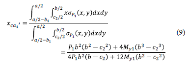
The center of gravity "xca1'" is obtained by the equation:
The moment around the axis a1'-a1' is:

Substituting the equation (8) and (9) into equation (10) is obtained:

2.2.1.2. Moment around the axis a2'-a2'
The resultant force "FRa2''" is obtained through the volume of pressure the area formed by the axis a2'-a2' with a width "b2 = c3+d" and the free end of the rectangular footing, where the higher pressure is presented:

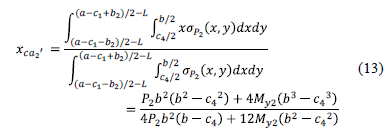
The center of gravity "xca2'" is obtained by the equation:
The moment around the axis a2'-a2' is:

Substituting the equation (12) and (13) into equation (14) is obtained:

2.2.1.3. Moment around the axis b'-b'
The resultant force "FRb'" is the force "P1" acting on column 1 less the volume of pressure the area formed by the axis b'-b' and the corners 1 and 2 to the left of the footing, this is presented of the follows:

The center of gravity "ycb'" with respect to axis b'-b' is:

The moment around the axis b'-b' is:

Substituting the equation (16) and (17) into equation (18) is obtained:

2.2.1.4. Moment around the axis c'-c'
First, the position of the axis c'-c' must be localized, which is where the maximum moment is located.
When the shear force is zero, the moment should be the maximum, then the shear force is presented at a distance "ym", this is shown as follows:

Now the equation (20) is equal to zero and we obtain:

Then the maximum moment is obtained as follows:

Substituting the equation (21) into equation (22) is:

2.2.1.5. Moment around the axis d'-d'
The resultant force "FRd'" is the force "P1" acting on column 1 less the volume of pressure the area formed by the axis d'-d' and the corners 1 and 2, which is found to the left of the footing, this is as follows:

The moment around the axis d'-d' is:

2.2.1.6. Moment around the axis e'-e'
The resultant force "FRe'" is the sum of the force "P1" acting on column 1 and the force "P2" acting on column 2 less the volume of pressure the area formed by the axis e'-e' and the corners 1 and 2, which is found to the left of the footing, this is as follows:

The moment around the axis e'-e' is:

2.2.2. Model to obtain the bending shear
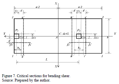
The critical sections for bending shear are obtained at a distance "d" starting the junction of the column with the footing as seen in Fig. 7, these are presented in sections f1'-f1', f2'-f2', g'-g', h'-h' and i'-i'.
2.2.2.1. Bending shear in axis f1'-f1'
Bending shear acting on the axis f1'-f1' of the footing "Vff1'" is obtained through the volume of pressure the area formed by the axis f1'-f1' with a width "b1 = c1+d/2" and the free end of the rectangular footing, where the greatest pressure is presented:

2.2.2.2. Bending shear in axis f2'-f2'
Bending shear acting on the axis f2'-f2' of the footing "Vff2'" is obtained through the volume of pressure the area formed by the axis f2'-f2' with a width "b2 = c3+d" and the free end of the rectangular footing, where the greatest pressure is presented:

2.2.2.3. Bending shear in axis g'-g'
Bending shear acting on the axis g'-g' of the footing "Vfg'" is the force "P1" acting on column 1 less the volume of pressure the area formed by the axis g'-g' and the corners 1 and 2 to the left of the footing, this is as follows:

2.2.2.4. Bending shear in axis h'-h'
Bending shear acting on the axis h'-h' of the footing "Vfh'" is the force "P1" acting in column 1 less the volume of pressure the area formed by the axis h'-h' and the corners 1 and 2, which is found to the left of the footing, this is:

2.2.2.5. Bending shear in axis i'-i'
Bending shear acting on the axis i'-i' of the footing "Vfi'" is the sum of the force "P1" acting on column 1 and the force "P2" acting on column 2 less the volume of pressure the area formed by the axis i'-i' and the corners 1 and 2, which is found to the left of the footing, this:

2.2.3. Model to obtain the punching shear
The critical section for the punching shear appears at a distance "d/2" starting the junction of the column with the footing in the two directions.
2.2.3.1. Punching shear for boundary column
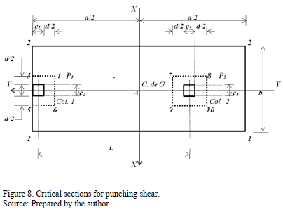
The critical section for the punching shear is presented in rectangular section formed by points 3, 4, 5 and 6, as shown in Fig. 8. Punching shear acting on the footing "Vp1" is the force "P1" which acting on column 1 less the volume of pressure the area formed by the points 3, 4, 5 and 6:

2.2.3.2. Punching shear for inner column
The critical section for the punching shear is presented in rectangular section formed by points 7, 8, 9 and 10, as shown in Fig. 8. Punching shear acting on the footing "Vp2" is the force "P2" which acting on column 2 less the volume of pressure the area formed by the points 7, 8, 9 and 10:

2.3. Classic model
This model takes into account only the maximum pressure of the soil for design of footings and it is considered uniform at all points on contact area of footings. The maximum pressure is:
- In the longitudinal direction:
- In the transverse direction:
v To the boundary column is:

v To the intermediate column is:
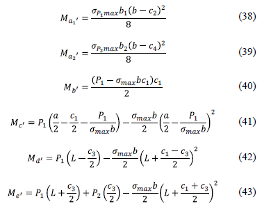
2.3.1. Model to obtain the moments
Critical sections for bending moments are shown in Fig. 6, these are presented in sections a1'-a1', a2'-a2', b'-b', c'-c', d'-d' and e'-e'. The bending moment in each section is:
2.3.2. Model to obtain the bending shear
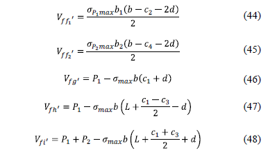
The critical sections for bending shear (seen in Fig. 7), these are presented in sections f1'-f1', f2'-f2', g'-g', h'-h' and i'-i'. The bending shear in each section is:
2.3.3. Model to obtain the punching shear
The critical sections for the punching shear are presented in Fig. 8.
v The punching shear for boundary column

v The punching shear for inner column

2.4. Procedure of design
Step 1: The mechanical elements (P, Mx, My) acting on the footing is obtained by the sum of: the dead loads, live loads and accidental loads (wind or earthquake) from each of these effects [20,21].
Step 2: The available load capacity the soil "sadm" is [20, 21]:

where: qa is the allowable load capacity the soil, gppz is the self-weight of the footing, gpps is the self-weight the soil fill.
Step 3: The value of "a" is selected according to the following equation:

where: a is the dimension of the parallel footing the axis "Y", R=P1+P2, Mx=Mx1+Mx2.
The value of "b" is:
To xR ≤ b/6:

To xR ≥ b/6:

where: b is the dimension of the parallel footing the axis "X", My=My1+My2.
Note: if in the combinations are included the wind and/or the earthquake, the load capacity the soil should be increased by 33% [18].
Step 4: The mechanical elements (P, Mx, My) acting on the footing are factored [18].
Step 5: The bending moments acting on the combined footing are obtained.
Step 6: The effective depth "d" for the maximum moment is found by the following expression [18]:

where: Mu is the factored maximum moment at section acting on the footing, Øfis the strength reduction factor by bending and its value is 0.90, bw is width of analysis in structural member, r is ratio of "As" to "bwd", fy is the specified yield strength of reinforcement of steel, f'c is the specified compressive strength of concrete at 28 days.
Step 7: Bending shear resisted by the concrete "Vcf" is [18]:

To bending shear acting on the footing (Vf) is compared vs. bending shear resisting by concrete (Vcf) and is [18]:

where: Øv is the strength reduction factor by shear is 0.85.
Step 8: Punching shear (shear force bidirectional) resisted by the concrete "Vcp" is given [18]:

where: bc is the ratio of long side to short side of the column and b0 is the perimeter of the critical section.

where: as is 40 for interior columns, 30 for edge columns, and 20 for corner columns.

where: ØvVcp must be the value smallest of equations (58a), (58b) and (58c).
To punching shear acting on the footing (Vp) is compared vs. punching shear resisting by concrete (Vcp) and must comply with the following expression [18]:

Step 9: The main reinforcement steel "Asp" is [18]:

where: w is 0.85f'c /fy.
The minimum steel "Asmin" and the minimum percentage "rmin" by rule are [18]:

The reinforcement steel by temperature is found [18]:

where: t is the total thickness of the footing.
Step 10: The development length in tension of deformed bars "ld" is expressed [18]:
Steel reinforcement in the top:

Steel reinforcement in the bottom:

where: yt is the traditional reinforcement location factor to reflect the adverse effects of the top reinforcement casting position, ye is a coating factor reflecting the effects of epoxy coating, dbis the diameter of the bars, l is modification factor reflecting the reduced mechanical properties of lightweight concrete, all relative to normalweight concrete of the same compressive strength.
The development length for deformed bars "ld" is compared vs. the available length of the footing "la" and must comply with the following expression [18]:

3. Application
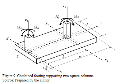
The design of a boundary combined footing supporting two square columns is presented in Fig. 9, with the basic information following: c1 = 40x40 cm; c2 = 40x40 cm; L = 6.00 m; H = 1.5 m; MDx1 = 140 kN-m; MLx1 = 100 kN-m; MDy1 = 120 kN-m; MLy1 = 80 kN-m; PD1 = 700 kN; PL1 = 500 kN; MDx2 = 280 kN-m; MLx2 = 200 kN-m; MDy2 = 240 kN-m; MLy2 = 160 kN-m; PD2 = 1400 kN; PL2 = 1000 kN; f'c = 21 MPa; fy = 420 MPa; qa = 220 kN/m2; gppz = 24 kN/m3; gpps = 15 kN/m3.
Where: H is the depth of the footing, PD is the dead load, PL is the live load, MDx is the moment around the axis "X-X" of the dead load, MLx is the moment around the axis "X-X" of the live load, MDy is the moment around the axis "Y-Y" of the dead load, MLy is the moment around the axis "Y-Y" of the live load.
Step 1: The
loads and moments acting on soil: P1 = 1200 kN; Mx1 = 240 kN-m; My1 = 200 kN-m; P2 = 2400 kN; Mx2 = 480 kN-m; My2 = 400 kN-m.
Step 2: The available load capacity the
soil: The
thickness "t" of the footing is
proposed, the first proposal is the minimum thickness of 25 cm marking regulations, subsequently the thickness is revised to
meet the following conditions: moments, bending shear and punching shear. If
such conditions are not satisfied is proposed a greater thickness until it
fulfills the three conditions mentioned. The thickness of the footing that
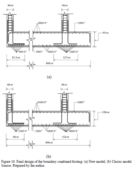
fulfills the three conditions listed above is 95 cm for new model and for classic model is 120 cm. Using the
equation (51) is obtained the available
load capacity of the soil "sadm" is 188.95 kN/m2 (new
model) and 186.70 kN/m2 (classic
model).
Step 3: The
value of "a" by equation (52) is
obtained: a = 8.00 m. The value of "b" by equation (53) is found: b
= 3.20 m. These values are for
the two models. This value of "b" is
verified to xR ≤ b/6 and meets.
Step 4: The mechanical elements (P, Mx,
My) acting on the footing is factored: Pu1 = 1640 kN; Mux1 = 328 kN-m; Muy1 = 272 kN-m; Pu2 = 3280 kN; Mux2 = 656 kN-m; Muy2 = 544 kN-m.
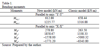
Step 5: The bending
moments acting on the footing of the two models are presented in Table 1.
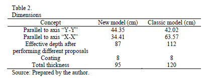
Step 6: The
effective depth for the bending moment is found by equation (55); these are
shown in Table 2.
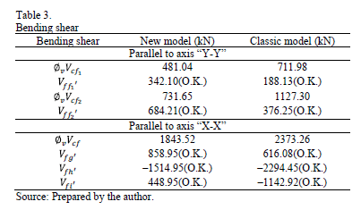
Step 7: Bending
shear appear in Table 3.
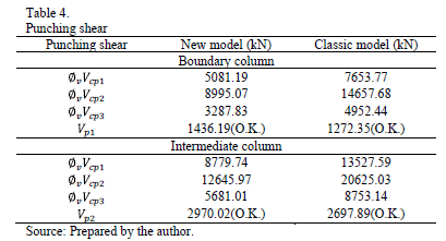
Step 8: Punching shear is presented in Table 4.
Step 9: The
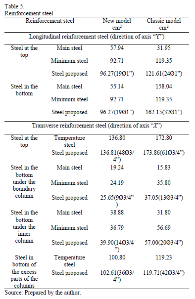
reinforcement steel is shown in Table 5.
Step 10: The
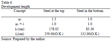
minimum development length for deformed bars appear in Table 6.
4. Conclusions
The foundation is a part essential of a structure, because permits the transmission of loads from the structure to the soil. The mathematical approach suggested in this paper produces results that have a tangible accuracy for all problems, main part of this research for find the solution more economical.
The proposed model presented in this paper for the structural design of boundary combined footings subjected
to an axial load and moment in two directions, also it can be applied to others cases: 1) The footings subjected to a concentric axial load, 2) The footings subjected to a axial load and moment in one direction.
The model presented in this paper applies only for design of boundary combined footings, the structural member is assumed to be rigid and the supporting soil layers elastic, which meet expression of the bidirectional bending, i.e., the variation of pressure is linear. The suggestions for future research, when is presented another type of soil, by example in totally cohesive soils (clay soils) and totally granular soils (sandy soils), the pressure diagram is not linear and should be treated differently (see Fig. 1).
References
[1] Bowles, J.E., Foundation analysis and design, McGraw-Hill, New York, 1996.
[2] Das, B.M., Sordo-Zabay, E. and Arrioja-Juárez, R., Principios de ingeniería de cimentaciones, Cengage Learning Latin America, México, 2006.
[3] Calabera-Ruiz, J., Calculo de estructuras de cimentación, Intemac Ediciones, México, 2000.
[4] Tomlinson, M.J., Cimentaciones, diseño y construcción, Trillas, México, 2008.
[5] Mosley, W.H., Bungey, J.H. and Hulse, R., Reinforced concrete design, Palgrave Macmillan, New York, 1999.
[6] Gambhir, M.L., Fundamentals of reinforced concrete design, Prentice-Hall, of India Private Limited, 2008.
[7] Kurian, N.P., Design of foundation systems, Alpha Science Int'l Ltd., India, 2005.
[8] Punmia, B.C., Kumar-Jain, A., and Kumar-Jain, A., Limit state design of reinforced concrete, Laxmi Publications (P) Limited, New Delhi, India, 2007.
[9] Varghese, P.C., Design of reinforced concrete foundations, PHI Learning Pvt. Ltd., New Delhi, India, 2009.
[10] Ibañez-Mora, L., Pruebas de carga no destructivas en pilotes, DYNA, 75 (155), pp. 57-61, 2008.
[11] Gaviria, C.A., Gómez, D. and Thomson, P., Evaluación de la integridad de cimentaciones profundas: análisis y verificación in situ, DYNA, 76 (159), pp. 23-33, 2009.
[12] Valencia, Y., Camapum, J. and Lara, L., Aplicaciones adicionales de los resultados de pruebas de carga estáticas en el diseño geotécnico de cimentaciones, DYNA, 175, pp. 182-190, 2012.
[13] Camacho-Tauta, J.F., Reyes-Ortiz, O.J. and Jimenez-Alvarez, J.D., Comparison between resonant-column and bender element test on three types of soils, DYNA, 80 (182), pp. 163-172, 2013.
[14] Luévanos-Rojas, A., A mathematical model for dimensioning of footings rectangular, ICIC Express Letters Part B: Applications, 4, pp.269-274, 2013.
[15] Luévanos-Rojas, A., A mathematical model for dimensioning of footings square, International Review Civil Engineering (IRECE), 3, pp.346-350, 2012.
[16] Luévanos-Rojas, A., A mathematical model for the dimensioning of circular footings, Far East Journal of Mathematical Sciences, 71, pp. 357-367, 2012.
[17] Luévanos-Rojas, A., Faudoa-Herrera, J.G., Andrade-Vallejo, R.A. and Cano-Alvarez, M.A., Design of isolated footings of rectangular form using a new model, International Journal of Innovative Computing, Information and Control, 9, pp. 4001-4022, 2013.
[18] ACI 318S-13 (American Concrete Institute), Building Code Requirements for Structural Concrete and Commentary, Committee 318, 2013.
[19] Gere, J.M. and Goodo, B.J., Mecánica de materiales, Cengage Learning, México, 2009.
[20] González-Cuevas, O.M. and Robles-Fernández-Villegas, F., Aspectos fundamentales del concreto reforzado, Limusa, México, 2005.
[21] McCormac, J.C. and Brown, R.H., Design of reinforced concrete, John Wiley & Sons, New York, 2013.
A. Luévanos-Rojas, received the BSc. Eng in Civil Engineering in 1981, the MSc degree in Planneation and Construction in 1996, and the Engineering Dr. degree in Planneation and Construction in 2009, all of them from the Facultad de Ingeniería, Ciencias y Arquitectura of the Universidad Juárez del Estado de Durango, Gómez Palacio, Durango, México. The MSc degree in Structures in 1983, from the Escuela Superior de Ingeniería y Arquitectura the Instituto Politécnico Nacional, Distrito Federal, México. The MSc degree in Administration in 2004, from the Facultad de Contaduría y Administración of the Universidad Autónoma de Coahuila, Torreón, Coahuila, México. From 1983 to 2009, he is a full time professor and from 2009 to 2014, he is professor and researcher for the Facultad de Ingeniería, Ciencias y Arquitectura of the Universidad Juárez del Estado de Durango. His research interests include: mathematical models applied to structures: methods of structural analysis, members design of concrete and steel, analysis of non-prismatic members. Also he is Associate Editor the journal "ICIC Express Letters Part B: Applications". ORCID: 0000-0002-0198-3614.
Cómo citar
IEEE
ACM
ACS
APA
ABNT
Chicago
Harvard
MLA
Turabian
Vancouver
Descargar cita
CrossRef Cited-by
1. Arnulfo Luévanos-Rojas, Blanca Lucia Estrada-Mendoza, Mónico Juárez-Ramírez. (2024). Estudio comparativo para áreas mínimas en contacto con el suelo de zapatas aisladas rectangulares y circulares trabajando parcialmente bajo compresión. Boletín de Ciencias de la Tierra, (55), p.85. https://doi.org/10.15446/rbct.n55.111624.
2. Arnulfo Luévanos Rojas. (2023). Nuevo modelo para el diseño completo de zapatas aisladas rectangulares tomando en cuenta que la superficie de contacto funciona parcialmente en compresión. Revista ALCONPAT, 13(2), p.192. https://doi.org/10.21041/ra.v13i2.671.
3. K. M. Aishwarya, N. C. Balaji. (2023). Analysis and design of eccentrically loaded corner combined footing for rectangular columns. ADVANCES IN SUSTAINABLE CONSTRUCTION MATERIALS. ADVANCES IN SUSTAINABLE CONSTRUCTION MATERIALS. 2759, p.050015. https://doi.org/10.1063/5.0144289.
Dimensions
PlumX
Visitas a la página del resumen del artículo
Descargas
Licencia
Derechos de autor 2014 DYNA

Esta obra está bajo una licencia internacional Creative Commons Atribución-NoComercial-SinDerivadas 4.0.
El autor o autores de un artículo aceptado para publicación en cualquiera de las revistas editadas por la facultad de Minas cederán la totalidad de los derechos patrimoniales a la Universidad Nacional de Colombia de manera gratuita, dentro de los cuáles se incluyen: el derecho a editar, publicar, reproducir y distribuir tanto en medios impresos como digitales, además de incluir en artículo en índices internacionales y/o bases de datos, de igual manera, se faculta a la editorial para utilizar las imágenes, tablas y/o cualquier material gráfico presentado en el artículo para el diseño de carátulas o posters de la misma revista.


