Publicado
Developing a self-regulating soldering iron based on induction heating
DOI:
https://doi.org/10.15446/dyna.v83n196.51208Palabras clave:
Electromagnetic induction, Heating, Resonant inverter, Soldering iron. (es)Descargas
DOI: https://doi.org/10.15446/dyna.v83n196.51208
Developing a self-regulating soldering iron based on induction heating
Desarrollo de un cautín autorregulable basado en calentamiento por inducción
Cuauhtémoc Mazón-Valadez, Luis Héctor Quintero-Hernández, Ernesto Edgar Mazón-Valadez, Alfonso Hernández-Sámano, José Ávila-Paz & Mario Eduardo Cano-González*
Centro Universitario de la Ciénega, Universidad de Guadalajara, México. mazon2065@hotmail.com, hectorquintero@yahoo.com, mazon_valadez@hotmail.com, h.s.alfonso@gmail.com, jocmos@hotmail.com, meduardo2001@hotmail.com*.
Received: June 11th, 2015. Received in revised form: January 18th, 2016. Accepted: January 26th, 2016.
This work is licensed under a Creative Commons Attribution-NonCommercial-NoDerivatives 4.0 International License.

Abstract
This work focused on the design,
development and construction of a new low cost soldering iron that works by
means of induction heating. The amount of electronic components has been
minimized in order to reduce production costs. Additional tests were undertaken
to determine the ideal tips for soldering, and the adaptations necessary to
guarantee self-regulation using a nickel foil shield (due to its low curie
temperature) are suggested. The new device contains a resonant inverter able to
generate alternating magnetic fields of 100 kHz at the center of an 18-turn coil; the inverter is controlled only using an
astable oscillator circuit. The paper examines criteria to select suitable
soldering-tips by experimentally determining their equivalent resistance
heating it within the resonant inverter or well, another one by using a rapid
magnetic test. The system represents a good tool, suitable for the manufacture
of development boards or electronic tasks.
Keywords: Electromagnetic induction; Heating; Resonant inverter; Soldering iron.
Resumen
Este trabajo
se enfocó en diseñar y construir un novedoso cautín económico que funciona
mediante inducción magnética. Se han minimizado la cantidad de componentes
electrónicos que lo conforman para disminuir su costo de producción y también
se realizaron pruebas para determinar las puntas óptimas para soldar,
proponiendo las adaptaciones necesarias para lograr la autorregulación
empleando una cubierta de lámina de níquel por su baja temperatura de Curie. El
nuevo dispositivo se compone de un inversor resonante capaz de generar campos
magnéticos alternos de 100 kHz en el
centro de una bobina de 18 espiras y éste se controla solamente con un circuito
oscilador astable. Se discute un criterio para seleccionar las puntas
reemplazables, basado en la resistencia equivalente obtenida experimentalmente
del inversor resonante o bien otro criterio haciendo un rápido ensayo
magnético. El nuevo dispositivo representa una herramienta adecuada para
realizar tarjetas impresas de circuitos o tareas de electrónica.
Palabras clave: Inducción Electromagnética; Calentamiento; Inversor Resonante; Soldador.
1. Introduction
Currently, the majority of the devices specially designed to heat by using resistance or any natural fuel have been replaced by their equivalent that work via induction heating. In most cases, the pieces to be heated are composed of ferromagnetic materials, which can be heated with electromagnetic waves of frequencies in the range of tens of kHz due to their high magnetic permeability [1], for example induction cookers [2], that use f ≈ 30 kHz. These new devices success is thanks to a non-invasive heating procedure, representing a cleaner method than the conventional ones [3]. Nevertheless, professional induction heating devices rely on more complex electronics technology and higher manufacturing costs.
Additionally, induction heaters are used in industrial applications for metallic pieces, such as dilatation, furnace welding [4] and sealing plastic bags [5]. Other new applications are focused on the development of biomedical therapies like magnetic hyperthermia for the treatment of tumors [6,7].
Recently, we made a pencil-style soldering iron characterized by the fact that no cord is used in the handle [8] and that it is designed to work intermittently, unlike other commercial high frequency soldering irons [9]. With this device, it is possible to comfortably solder electronic components onto printed circuit boards (PCB), mostly by melting lead/tin wire or ecologic solder paste. The system is enhanced by a specially constructed resonant inverter that can achieve efficiencies up to 95 %.
The main aim of this work is to develop a new induction heating soldering iron for continuous use, keeping costs low to make it viable for reproduction on an industrial scale. The principal idea is to simplify the electronic stages in the control of its high power electronic circuit. Moreover, by introducing a low Curie temperature material, the need to use control electronics to limit temperature is reduced. Also, some other considerations are taken into account so the system is capable of heating a set of inexpensive commercial tips, which are typically used in resistance soldering irons.
2. Theoretical background
2.1. Induction heating
The heating process of a soldering tip using an electromagnetic wave through an induction coil, can be reduced to the problem of an AC current flowing in a cylindrical conductor rod with radius a, where a current flow known as Eddy currents is induced [10]. Indeed, if the tip is ferromagnetic it could be heated using frequencies in the range of tens or hundreds of kHz; Fig. 1(A) shows the procedure where the ferromagnetic piece is placed inside the region of magnetic flux. The magnetic field is generated using a coil with N loops, length l and inductance L, which is powered with an AC power supply of high frequency. Since the magnetic permeability m of the metal depends on the temperature, its ferromagnetic behavior could vanish at the Curie point (Curie temperature TC), where it becomes a paramagnetic material [11,12] and the inductance of the work coil tends to L, because the material reaches the permeability of an empty space m0.

A complete analysis of the heating of several types of materials with radiofrequencies was undertaken by Brown [13], here it is observed that the magnitude of the magnetic field intensity H in the rod satisfies the eq. (1).

where f is the frequency of the wave, m is the magnetic permeability and s is the conductivity of the material. The solutions to this equation are the typical Bessel functions of first class and order zero, expressed in eq. (2) [13].

where the constant A depends on the initial conditions and
on the skin thickness in the material s [14]; which is given by eq. (3). Physically, this value represents the
effective surface of the material with resistivity , where the electric current crosses.

Following the Maxwell-Ampere law [15] and neglecting the dielectric constant of the material, it is possible to obtain a relationship between the electric field due to the induced currents on the material and the external magnetic field intensity; this is given by eq. (4).

Then, using the solutions of eq. (2) on eq. (4) it
is possible to determine the superficial power dissipated ( ) for the ferromagnetic rod in watts per unit length, as
expressed in eq. (5) [15].
) for the ferromagnetic rod in watts per unit length, as
expressed in eq. (5) [15].

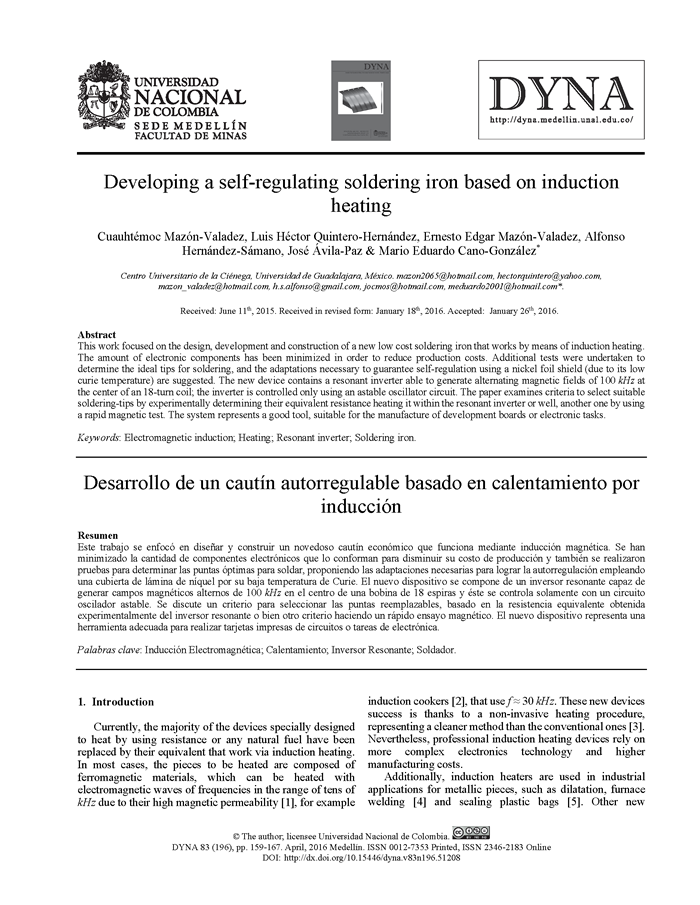
With a further analysis of the Bessel polynomials the solution for H is obtained, assuming uniform magnetic field intensity H0, parallel to the flux direction in all the metal [13], to apply boundary conditions. Thus, the value of P is obtained as shown in eq. (6).
The ratio  is known as the
superficial resistance and it can be clearly observed that by diminishing the
value s and maintaining the same
electric current, the power dissipated in the material P is increased. Nevertheless, the value of s depends on the electromagnetic properties of the material and the
applied frequency.
is known as the
superficial resistance and it can be clearly observed that by diminishing the
value s and maintaining the same
electric current, the power dissipated in the material P is increased. Nevertheless, the value of s depends on the electromagnetic properties of the material and the
applied frequency.
Regarding soldering iron tips, the first point to be noted is that they are composed of at least three layers as displayed in Fig. 1(B), where the most superficial is made of Chrome (Cr) which is used to reduce corrosion and has a thickness of approximately 10 mm [16]. The next layer could be composed of a hard ferromagnetic material such as iron or nickel to increase the duration of the tip, with a thickness of 200 mm [17]. Finally these layers are covered by a thicker solid piece of copper, to increase the thermal diffusivity of the tip and therefore the eq. (6) takes different values in each of its layers.
2.2. Electromagnetic field generator
Usually, the generation of electromagnetic fields employed in induction heating is carried out with power electronic circuits known as resonant inverters. These circuits are composed of an array of semiconductors to switch the current and feed a resonant circuit. TTL technology is used in the human audible interval of frequencies; IGBT can be used up to 200 kHz and MOSFET technology up to 1MHz. They can be configured as "H-bridge" (half or whole) or "push pull", to feed a series or parallel LC circuit or "resonant tank" [18]. In general the tank resonates when the difference between its capacitive and the inductive reactance is null. The commutation of the transistors is controlled using a driver circuit to adjust the duty cycle and dead time of the transistors, which include a pre-amplification stage connected to another electronic circuit in order to isolate the driver of the switching stage [19,20]. Also, in some applications, current sensors to complement a phase lock loop stage (PLL) or a frequency compensation circuit, connected between the tank and the driver circuit [21,22] are used. All these electronic components and the engineering involved, in some devices force an increase in production costs, making it unviable to be manufactured on an industrial scale. In contrast with devices that work with fuel or resistances, where the engineering work is less complex and involves lower costs. Nevertheless as the Eddy currents produced for induction heaters are focused mainly on the heated metal piece, this technology could be more energy saving.
With a view to simplifying the resonant inverter, in this research the circuit displayed in Fig. 2 is built. It is a class D voltage-switching inverter with half H-bridge topology, with the resonant capacitor divided into two halves [23-25]. Also, a pair of mosfets transistors Q1 and Q2 (N-channel and P-channel respectively) are used to switch the current to a LRCR series resonant circuit (CR = CR1+CR2), each transistor gate is driven directly (through a simple resistance RG) with a cheap astable oscillator. While the high value of the rectangular signal activates the N-channel mosfet and closes the P-channel, the low side has the opposite effect. The whole circuit is powered with an AC to DC adapter with a tension VDC.

It is important to note that the ideal resonant frequency of this circuit satisfies eqs. (7), where LR and CR are the resonant inductance and capacitance respectively.

Meanwhile, the power delivered to the ferromagnetic tip by this circuit when the inverter is supplied with VI is given by the eq. (8).

where IR is the resonant current through LR and q the phase shift angle with respect to VI. From another point of view, the power dissipated on the surface of the ferromagnetic piece with resistance RF, due to the Eddy currents IF, also obeys the Joule law and then the eq. (8) is equivalent to the eq. (9).

Analysing eq. (8) and taking into account that the magnetic field H0 is related with IR in a coarse approximation and the properties of the induction coil LR, through the eq. (10).

Thus the eq. (6) is rewritten as the eq. (11) and regarding the shape of eq. (9) it is possible to find an expression for the equivalent resistance of the resonant inverter R as the eq. (12), including the total static resistance of all the electronics components Rdc.

3. Materials and Methods
3.1. Industrial design of the new soldering iron
As a starting point, the handle of a commercial soldering iron with a pencil design based on a resistance is used; thus, a new set of pieces was adapted to work via magnetic induction. Fig. 3(A) shows the design of the new soldering iron, which contains a thermal insulating plastic handle (1), a cylindrical cavity of nonmagnetic stainless steel (2) to cover the new set of components and attach them to the handle, a cylindrical cavity of solid Teflon (3) to hold an end of the tip (8), which is inserted in a cylindrical nickel foil cavity of 200 mm thickness (7), both pieces cross through the coil center (4), isolating it from the tip and form the external shield (2) using a cylindrical cavity of silicone (5), able to resist up to 350°C, but maintaining a vacuum space to reduce the risk of the coil being heated by the tip. Finally the conical edge of the tip is clamped to a small cylindrical cavity of Teflon (6).

The final presentation of the new pencil soldering iron is displayed in Fig. 3(B), with a shape similar to the original resistance soldering iron. Fig. 3(C) also shows the cabinet with the circuit explained in Fig. 2, excluding the resonant coil (4). Moreover, the AC/DC adapter to power the circuit, a station to place the pencil and a set of 3 models of soldering tips, which are selected following the criterion explained in the next section, can also be seen in the same Fig. 3(C).
As is observed in Fig. 1, the soldering tip (6) and its nickel cavity (7) are heated directly by the resonant coil taking advantage of their ferromagnetic properties and without physical contact, with the aim of transmitting all the dissipated power on the tip, to the solder wire.
3.2. Selecting the soldering tips
As illustrated in Fig. 1(B) the soldering tips are composed mainly of Cu (diamagnetic material), they are also coated with a ferromagnetic material (Ni or Fe) and in the external surface the shield is Cr (paramagnetic material). We obtained three inexpensive soldering tips (brand Steren), Cu, cone shaped and with the following specifications: CAU-118 with 67 mm length and major diameter 3.6 mm; CAU-192 with 58 mm length and major diameter 4.5 mm; and CAU-151 with 70 mm length and major diameter 3.6 mm. However, the provider does not provide clear information about the materials involved in the coating of the tips. Table 1 displays the electromagnetic properties and the thermal diffusivity of the materials that characterize the soldering tips.

Since Cu and Cr have a small magnetic permeability mr, higher frequencies (near to MHz) are necessary to reach a small s value, as is required in the eq. (6) to dissipate a major P value. So, there is more benefit to heating the tip with a high frequency f constraining the current to a small s value in the ferromagnetic coating, which offers a quite large resistivity r. Additionally, as the thermal diffusivity of Cu is almost one magnitude order higher than for Ni of Fe, it is more practical to transmit the temperature faster to the solder wire through this means.
Regarding the cylindrical piece (7) detailed in Fig. 3(A) and developed to cover the welding tips; it was made with a pure Ni foil and has a 0.2 mm thickness. This is used to increase the effective diameter of the tips CAU-118 and CAU-151. Indeed this piece is used intentionally in order to achieve self-regulation of the tips, due to its low Curie temperature Tc = 325 °C. In this sense, when this piece and the whole tip reach this temperature, the relative permeability of Ni falls very close to mr = 1, then the value of s in all the layers of the tip are increased and the value of P diminish dramatically and the heating rate collapses. After the temperature of the tip decreases bellow Tc, the value of s diminishes in the Ni shield and therefore the P value increases and begins heating faster again.
In order to find the best frequencies to heat the tips, we conducted an exhaustive experimental assessment by using an alternative experimental setup, suitable to cover a wide range of radiofrequencies to heat them and measure their temperature simultaneously with an infrared sensor [8], finding a value approximately of f = 100 kHz. In addition, a characterization of their magnetic properties was made by using a vibrating sample magnetometer (VSM) [26].
3.3. Electronic features of the soldering iron
A rectangular signal of f = 100 kHz (in accordance with the last part of the previous section), with 15 V of amplitude and 50 % duty cycle is generated with a commercial astable multivibrator of CMOS technology. The integrated circuit CD4047 is configured using a resistance R1 = 22 kW and a capacitor C1 = 100 pF, powered with VCC = 15 V. Fig. 4 shows the diagram of the electronic circuit that was developed.

This rectangular voltage of the oscillator directly feeds both gate terminals of the FQA12P20 and IRFP450 mosfets, through a resistance RG = 10 W at the same time. Both transistors form the voltage inverter (see Fig. 2). When the mosfet Q1 sends current through the work coil (N = 18 turns and 5 cm length l, resulting on a LR = 1.3 mH), the current crosses in one sense closing the circuit at the capacitors bank node CR2 =1010 nF, the other capacitors bank CR1 = CR2, works as a parallel capacitor connected by short circuit to the AC voltage source and blocking the DC components to LR. A similar behaviour happens when the mosfet Q2 provides the current to LR in the opposite direction. This commutation at 100 kHz allows the resonance of the LRCR circuit due to the established values in the eq. (7), generating a sinusoidal waveform.
4. Experimental Results and Discussions
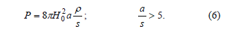
After the electronic design, a main board with all the electronic components is engraved to weld; Fig. 5(A) shows the simulation in the PSPICE platform, in order to analyze the behavior between the driver signal and the resonant current. The simulation suggests a small deformation of the sinusoidal waveform due to the absence of a dead time in the ON and cut-Off state of both mosfets. Moreover Fig. 5(B) is obtained experimentally using an oscilloscope with a USB port and through flash memory; in this experiment the LR has no soldering tip. Two overlapped waveforms, the mosfets driver signal (the rectangular shape) and the quasi-sinusoidal waveform of the resonant current are displayed here. Additionally, a good concordance between the resonant currents amplitudes obtained in these two ways was observed, with relative differences of 8 %.

Continuing with the characterization of the device, the resonant current (gray line) and voltage (dark line) signals are obtained using the PSPICE and the waveforms are shown in Fig. 6(A). As is expected, the sinusoidal current is a little deformed and also, the voltage rectangular shape is strongly modified due to counter electromotive force induced by LR. The results of the corresponding experiment are displayed in Fig. 6(B). In this figure a set of four signals measured simultaneously is exhibited, where the uppermost corresponds to VDC which clearly is not the initial constant signal, this behavior is also observed in the signal placed immediately below. These two observations highlight the interference of the power supply with the resonant circuit and a simple calculus of their RMS values gives a power consumption of 67.4 W. The next two signals displayed below in the same figure are the resonant voltage and current respectively, the rectangular waveform of the voltage is strongly deformed in agreement with the simulation, but in this experiment a phase shift of 19.6° between both waveforms is observed and the output total power (eq. (8)) is approximately 59.0 W, indicating an efficiency of h = 88 %. The value used of R = 0.99 W is due to the total sum of the resistances of Q1 and Q2 (0.47 W each), plus the resistance of the coil of 0.05 W and neglecting the resistance RC which is very short to be determined.
On the other hand, in Figs. 7(A-C) the corresponding four signals obtained from the resonant coil are displayed, in a time instant when the tips CAU-118, CAU-151 and CAU-192 are heated, respectively. A quick analysis of these measurements indicates that the counterelectromotive forces are weakened when the CAU-192 is heated, because the amplitude of the ripple induced in the waveform of the power current ADC, is less than each other measurements. Furthermore, the voltage difference between the resonant coil terminals has a trend to a more rectangular signal than each other. This phenomenon is due to the marked difference of the magnetic properties observed for CAU-192 in comparison with the other tips [26]; this implies a major equivalent resistance R in the resonant inverter. Table 2 summarizes the efficiency values determined and equivalent resistance of this RF generator, in a time instant when each soldering tips is heated. The system responds with a major efficiency with the CAU-192.


After the analysis of the efficiency and equivalent resistance of the resonant inverter including the soldering tips, a last experiment is conducted to explore the self- regulation of the new soldering iron. With the aim of not overloading the thermal capability of the isolating pieces explained in Fig. 3(A), an AC/DC adapter of 12 V and 35 W maximum is used to avoid a possible overheating of the tips. In this experiment the heating curves of the tips (T vs t) are obtained connecting the output of an infrared sensor to one analogical channel of a National Instruments acquisition card in the platform of Lab-view DAQ-USB-6008. Fig. 8 shows these curves and an asymptotic behaviour in the heating of the curves CAU-118 and the CAU-151 is clearly observed. The temperature remains constant after three minutes of operation with a value near to 305 °C and 315 °C, due to the Curie temperature of the nickel-shield on these soldering tips. Although a maximum temperature of 325 °C is expected, this indicates the existence of a temperature gradient of 20 °C and 10 °C between the section of the tips submitted to the magnetic field (here the magnetic field is higher and then the heating is concentrated in this segment) and the conic extreme, respectively. Indeed, the curve of the CAU-192 never manifests an asymptotic behaviour in the temperature, indicating the absence of nickel in this tip and therefore its inner coating is based on iron. In other words, although the electromagnetic field generator has a higher efficiency when using CAU-192, it is not recommended to be used with our new self-regulated soldering iron. Furthermore, to extend its life time any other soldering tip of iron with equivalent resistance greater than R = 1.9 W is not recommended, nevertheless further experiments with a lot of different models of welding tips are needed to support this statement.

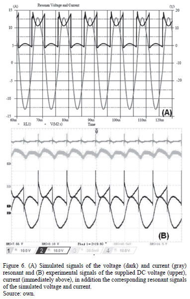
On the other hand, if we observe the heating during the first 60 s in Fig. 8, an increment above 150 ºC is recorded. This is not observed in similar measurements under the same conditions with CAU-118 and CAU-115 when the Ni cover is removed. As is displayed in Fig. 9, the increase in their temperatures does not exceed 20 ºC and 40 ºC respectively, and then their faster heating of Fig. 8 is principally due to the Ni cover, which is not necessary for CAU-192.
With the aim of establishing a criterion to select the most suitable soldering tips from those available on the electronics market, the magnetization curves of each tip are determined using a vibrating sample magnetometer Lakeshore 7300 and a cylindrical piece of 5 mm length extracted from each tip. The applied magnetic field ranges between ± 9 kOe and Fig. 10 shows the measurements.

Analysing the trends of magnetic saturation in each curve, for example to 8 kOe, the next values are observed (in emu/g): 10, 5.1 and 0.6 to the CAU-192, CAU-151 and CAU-118 respectively. Therefore, CAU-192 is the most magnetic tip as can be expected due to its composition of Fe as previously observed in Fig. 8, thus it is strongly attracted by a small magnet of NdFeB in comparison with CAU-118, which is hardly attracted by the same magnet. With this magnetic behavior, CAU-118 becomes a suitable candidate to be covered by the cylinder of Ni, following a sure and rapid criterion to ensure its self-regulation. For its part CAU-151 is also moderately attracted by the magnet and is more difficult to define a fast criterion to select it, one possibility is undertaking a quick test in the system to confirm the behavior exhibited in Fig 9.
5. Conclusions
The design and build of an inexpensive soldering iron, characterized because it works via induction heating is presented in this paper. The magnetic field generator of this device is a very simplified resonant inverter which excludes a lot of electronic stages, trying to diminish the production costs on an industrial scale. Indeed, the device is controlled just with a commercial oscillator circuit of CMOS technology. The final presentation of the device is like the traditional pencil-shape resistance soldering irons. Moreover, a set of three different soldering tips of Cu covered with ferromagnetic materials have been analysed to accompany the new device and it is possible to define a criterion to select them based on the equivalent resistance, determined by using the resonant inverter (under the value of Rdc = 0.99 W), i.e. 0.61 W < R ≤ 0.91 W. A tip of Cu coated in Fe with a major resistance could not achieve self-regulation even when covered with Ni. Therefore, we do not recommend using these tips with this device. If the equivalent resistance is approximated to 0.61 W, a cover of pure Ni with a thickness of 200 mm on the tip is recommended to ensure self-regulation at a temperature near to 325 °C. Another criterion to select a replacement soldering tip based on Cu, that is covered with a piece of Ni and is self-regulating, is by means of a fast and qualitative method using a small magnet to confirm its weak magnetic interaction or attraction, indicating a very small presence of ferromagnetic material in the coating (because the Cu and Cr are diamagnetic and paramagnetic respectively), in comparison with another piece with abundant Fe which again is not recommended for this system.
The estimated production cost of the device is approximately US$ 25. This calculation only takes into account the price of all the pieces and includes all the components and accessories displayed in Fig. 3(A) and Fig. 3(C). Finally, this device is a very useful tool in any electrical workshop or instrumentation laboratory, to perform technical repair works or electronics.
Acknowledgments
All the authors are grateful to the Mexican institution CONACYT for its valuable support.
References
[1] Field, A.B., Eddy currents in large slot-wound conductors. American Institute of Electrical Engineers, Transactions 26, pp. 761-788, 1905. DOI: 10.1109/PAIEE.1905.6742159.
[2] Burdío, M., Monterde, F., Garcia, J.R., Barragan, L.A. and Martinez, A., A two-output series-resonant inverter for induction-heating cooking appliances. Power Electronics, IEEE Transactions on, 20(4), pp. 815-822, 2005. DOI: 10.1109/TPEL.2005.850925.
[3] Boadi, A., Tsuchida,Y., Todaka,T. and Enokizono, M., Designing of suitable construction of high-frequency induction heating coil by using finite-element method. Magnetics, IEEE Transactions, 41(10), pp. 4048-4050, 2005. DOI: 10.1109/TMAG.2005.854993.
[4] Bayíndír, N.S., Kükrer, O. and Yakup, M., DSP-based PLL-controlled 50-100 kHz 20 kW high frequency induction heating system for surface hardening and welding applications. IEE Proceedings - Electric Power Applications, 150(3), pp. 365-371, 2003. DOI: 10.1049/ip-epa:20030096.
[5] Grooms, J.P. and Mattson, L.J., Method for induction sealing an inner bag to an outer container, US 5416303A, [Online]. 16 May 1995. http://www.google.st/patents/US5416303.
[6] Jordan, A., Scholz, R., Maier-Hauff, K., Johannsen, Wust, M., Nadobny, P.J., Schirra, H., Schmidt, H., Deger, S., Loening, S., Lanksch, W. and Felix, R., Presentation of a new magnetic field therapy system for the treatment of human solid tumors with magnetic fluid hyperthermia. Journal of Magnetism and. Magnetic. Materials, 225(1-2), pp. 118-126, 2001. DOI: 10.1016/S0304-8853(00)01239-7.
[7] Cano, M.E., Barrera, A., Estrada, J.C., Hernandez, A. and Córdova, T., An induction heater device for studies of magnetic hyperthermia and specific absorption ratio measurements. Review of Scientific Instruments, 82(11), pp. 114904-114904-6, 2011. DOI: 10.1063/1.3658818.
[8] Mazón-Valadez, Ernesto Edgar, et al. Developing a fast cordless soldering iron via induction heating. DYNA 81(188), pp. 166-172, 2014. DOI: 10.15446/dyna.v81n188.41635.
[9] Miyazaki, M., System and method for induction heating of a soldering iron, US/2010/0258554 A1, October 14 of 2010.
[10] Snown C., Alternating current distribution in cylindrical conductors, en Scientific Papers of the Bureau of Standards, USA, Washington, [Online]. 1925. 277. http://www.google.com/patents/US20100258554.
[11] Buschow, K.H.J., Encyclopedia of Materials: Science and Technology. Michigan: University of Michigan, 8, Elsevier, 2001.
[12] Kittel, C., Introduction to Solid State Physics, New York: John Wiley & Sons, 6th Ed, 1986.
[13] Brown, G.H., Hoyler, C.N. and Bierwirth, R.A., Theory and applications of the radiofrequency heating, New York: D. Van Nostrand Company, 1947.
[14] Dwight, H.B, A precise method of calculation of skin effect in isolated tubes. Journal of the American Institute of Electrical Engineers, 42(8), pp. 827-831, 1923. DOI: 10.1109/JoAIEE.1923.6593471.
[15] Jackson J.D., Classical Electrodynamics, New York: Wiley, 3rd Ed. 1998.
[16] Yoshimura, K., et al. Soldering iron with replaceable tip. U.S.
[17] Patent No. 8,569,657. [Online]. 29 Oct. 2013. Available at: http://www.google.ms/patents/WO2005115670A2?cl=en.
[18] Kent, G.M., Method of manufacturing replaceable soldering iron tips. U.S. Patent No. 3,315,350. [Online]. 25 Apr. 1967. Available at: https://www.google.com/patents/US3315350.
[19] Llorente, S., Monterde, F., Burdio, J.M. and Acero, J., A comparative study of resonant inverter topologies used in induction cookers, Applied Power Electronics Conference and Exposition, 7th. Annual IEEE, pp.1168-1174, 2002. DOI: 10.1109/APEC.2002.989392.
[20] Ye, Z., Jain, P.K. and Sen, P.C., Full-bridge resonant inverter with modified phase-shift modulation for high-frequency AC power distribution systems, IEEE Transactions on Industrial Electronics, 54(1), pp. 2831-2845, 2007. DOI: 10.1109/TIE.2007.896030.
[21] Goya, G.F., Cassinelli, N. and Ibarra-García, M.R., Magnetic hiperthermia application device, PCT/ES2009/000235, [Online]. November 12 of 2009. Available at: https://www.google.com/patents/EP2283895A1?cl=en&dq=Magnetic+Hyperthermia+Application+Device&hl=es-419&sa=X&ved=0ahUKEwitspiKq8bKAhXCRCYKHW90DaYQ6AEIIDAA.
[22] Calleja, H., Fast response control circuit for resonant inverters, International Journal of Electronics, 89(3), pp. 233-244, 2002. DOI: 10.1080/00207210210122550.
[23] Kamli, M., Yamamoto, S. and Abe, M., A 50-150 kHz half-bridge inverter for induction heating applications. IEEE Transactions on Industrial Electronics, 43(1), pp. 163-172, 1996. DOI: 10.1109/41.481422.
[24] Tai, Ch.-Ch. and Chen, M.K., The design of a half-bridge series-resonant type heating system for magnetic nanoparticle thermotherapy. PIERS [Online] 4 (2) pp. 276-280, 2007. DOI: 10.2529/PIERS070907021847.
[25] Hincapié, J.N. et al. Electrónica de potencia para el calentamiento por inducción doméstico: Revisión del estado del arte, Ingeniería y Ciencia, [Online] 9(18), pp. 237-262, 2013. Available at: http://www.scielo.org.co/pdf/ince/v9n18/v9n18a14.pdf.
[26] Tai Ch.-Ch. and Cheng, M.-K., Anti-interference design of quasi-resonant tank for magnetic induction heating system. PIERS, [Online]. 4(2) pp. 417-420, 2008. DOI: 10.2529/PIERS070907021437.
[27] Mazón-Valadez, E.E. et al., Comparison between the heating rates of a magnetic induction soldering iron and another one composed of resistance, Soldagem & Inspeção 20(2), pp. 228-237, 2015. DOI: 10.1590/0104-9224/SI2002.10.
C. Mazón-Valadez, received his BSc. degree in 2015 from the Universidad of Guadalajara, México in the Centro Universitario de la Ciénega of the Universidad de Guadalajara. His research interests include: Administration Technology. ORCID: 0000-0001-7989-6935.
L.H. Quintero-Hernández, received his PhD in Administration in the Centro Universitario de Ciencias Económico-Administrativas. His research interests include: Small and Medium Enterprises, also design and development of technological innovation. ORCID: 0000-0002-9222-927X.
E.E. Mazón-Valadez, received his MSc. degree in Exact Sciences and Engineering in the Centro Universitario de la Ciénega of the Universidad de Guadalajara, México. His research interests include: Magnetic Hyperthermia, Resonant Inverters and SAR. ORCID: 0000-0002-0553-5325.
A.Hernández-Sámano, received his MSc. Phys degree in 2013 from the University of Guanajuato, México, he is a PhD. student in Physics in the Centro Universitario de la Ciénega of the Universidad de Guadalajara, México. His research interests include: Magnetic Hyperthermia, Resonant Inverters and Magnetism. ORCID: 0000-0003-2684-313X.
J. Ávila-Paz, received his PhD. in 2015 from the Centro Universitario de la Ciénega of the Universidad de Guadalajara, México. He is currently professor in the Department of Technologic Sciences at the same university. His research interests include: magnetic hyperthermia, automation and control, and embedded systems. ORCID: 0000-0002-4358-1090.
M.E. Cano-González, received his PhD. degree in Physics in 2007 from the University of Guanajuato, México. He is Full professor in the Basic Sciences department in the Centro Universitario de la Ciénega of the Universidad de Guadalajara, México. His research interests include: magnetic hyperthermia, resonant inverters and Monte Carlo simulations. ORCID: 0000-0002-3334-0082.
Cómo citar
IEEE
ACM
ACS
APA
ABNT
Chicago
Harvard
MLA
Turabian
Vancouver
Descargar cita
CrossRef Cited-by
1. Mou Chatterjee, Sandip Pal. (2025). Design and performance evaluation of magnetic hyperthermia instrument with embedded PI control. Electromagnetic Biology and Medicine, 44(4), p.434. https://doi.org/10.1080/15368378.2025.2524547.
Dimensions
PlumX
Visitas a la página del resumen del artículo
Descargas
Licencia
Derechos de autor 2016 DYNA

Esta obra está bajo una licencia internacional Creative Commons Atribución-NoComercial-SinDerivadas 4.0.
El autor o autores de un artículo aceptado para publicación en cualquiera de las revistas editadas por la facultad de Minas cederán la totalidad de los derechos patrimoniales a la Universidad Nacional de Colombia de manera gratuita, dentro de los cuáles se incluyen: el derecho a editar, publicar, reproducir y distribuir tanto en medios impresos como digitales, además de incluir en artículo en índices internacionales y/o bases de datos, de igual manera, se faculta a la editorial para utilizar las imágenes, tablas y/o cualquier material gráfico presentado en el artículo para el diseño de carátulas o posters de la misma revista.