Publicado
Comparison of the Fire Resistance of two Structural Wall Systems in Light Steel Framing
DOI:
https://doi.org/10.15446/dyna.v84n201.57487Palabras clave:
Fire resistance, light steel frame, fire-resistant plasterboard (en)Descargas
The technological development of civil construction sector has led to the exploration of industrialized building systems. One of this system is the structural Light Steel Framing (LSF), which consists in cold formed steel frames juxtaposed with drywall enclosure of different materials, such as cement boards, wood boards and plasterboards. Despite of the advantages of this system, there is still a concern about their fire safety. Therefore, this paper aimed to verify the fire resistance of LSF systems with two types of plasterboard, one composed of standard plasterboard (common) and the other one by fire-resistant plasterboards. The samples were tested according to the ISO 834-1 standardized fire curve (ISO, 2014). During the tests, it was evaluated integrity, thermal insulation and structural stability of each solution. The results presented the system with fire-resistant plasterboards more secure when compared to the standard plasterboard (common). In both cases, the sample’s failure occurred due to the loss of integrity in the panels' joints.
Recibido: 8 de junio de 2016; Revisión recibida: 13 de diciembre de 2016; Aceptado: 30 de enero de 2017
Abstract
The technological development of civil construction sector has led to the exploration of industrialized building systems. One of this system is the structural Light Steel Framing (LSF), which consists in cold formed steel frames juxtaposed with drywall enclosure of different materials, such as cement boards, wood boards and plasterboards. Despite of the advantages of this system, there is still a concern about their fire safety. Therefore, this paper aimed to verify the fire resistance of LSF systems with two types of plasterboard, one composed of standard plasterboard (common) and the other one by fire-resistant plasterboards. The samples were tested according to the [1]. It was evaluated integrity, thermal insulation and structural stability of each solution. The results presented the system with fire-resistant plasterboards more secure when compared to the standard plasterboard (common). In both cases, the sample’s failure occurred due to the loss of integrity in the panels' joints.
Keywords:
Fire resistance, light steel frame, fire-resistant plasterboard.Resumen
El desarrollo de la construcción civil ha llevado a sistemas de construcción industrializados. Uno de estos es el Light Steel Framing (LSF), marcos de acero conformados en frío yuxtapuestos con cerramiento de paneles de tableros de cemento, madera o placas de yeso. Todavía hay una preocupación acerca de su seguridad contra incendios. Este estudio objetivó verificar la resistencia al fuego de los sistemas de LSF con dos tipos de placas de yeso, uno compuesto por placas estándar y el otro con yeso resistentes al fuego. Las muestras fueron analizadas a través de la curva de fuego [1]. Durante las pruebas, se evaluó la integridad, aislamiento térmico y estabilidad estructural de cada solución. Los resultados presentaron el sistema con placas de yeso resistentes al fuego más seguro que la placa de yeso estándar. En ambos casos, el fracaso fue debido a la pérdida de integridad de las articulaciones de los paneles.
Palabras clave :
Resistencia al fuego, light steel frame, placas de yeso resistentes al fuego.1. Introduction
The growth of construction market in industrialized countries has increased the use of innovative construction systems into residential buildings. Buildings with reduced costs and more efficient construction process is a real need in the industry. In order to fulfill this purpose the sector is heading industrial processes [2]. However, the performance of these alternatives must be analyzed and tested to evaluate its use as a building system [3,4], since its use is growing in the world [2]. Every system must meet the minimum performance requirements for its use, such as those prescribed by the standards [5,6].
The [5] and [6] have a mainly qualitative approach and it is based on the minimum requirements of (a) sustainability, (b) housing and (c) safety of the building and its systems [4,7]. Among the safety requirements there is the fire resistance of structural systems. In the event of a fire, a structural system should not compromise the evacuation of users, nor the integrity of the surrounding buildings and the work of rescue teams [8]. The minimum fire resistance time of these systems is a function of time, occupation and use of the building. However, the Light Steel Framing (LSF) systems present a short resistance period of time when exposed to a fire situation [9]. In some cases, these systems do not meet the minimum safety conditions [10].
LSF is one of the structural systems not specified by fire design standards. It is a building system structured with cold shaped galvanized steel frames coated with treated boards, which together form partition systems able to withstand the design actions. Depending on the slenderness of these frames, these systems may have a structural function. Since it is an industrialized and dry construction system, the LSF has great execution speed and material's rationalization [3], and promotes a foundation relief due to its low total weight. On the other hand, there is still a gap on testing and employability research studies, despite of the increase in its use in the market [11]. It was noted that there is still hesitation about its actual performance as building system [12], as their behavior in a fire situation and its effective applicability in this condition [11].
Recognized as a lightweight construction system, it is characterized by its low fire resistance, which can be improved by the use of special materials. The behavior of this type of system is connected to several parameters, especially on its configuration and/or type of panel, geometric aspect and the load rate applied [13], which makes harder to understand their actual behavior in a fire situation. The deduction of this set of factors emphasizes the need of carrying out fire resistance experimental studies and the knowledge of their behavior during a fire [11].
The fire resistance evaluation of a structural wall system is standardized by the [14-17]. These standards generally states that three conditions must be meet: (a) integrity, (b) thermal insulation, and (c) structural stability. During the tests, the furnace shall conform to a standardized rise of temperature, such as [1]. This curve is a well-accepted simulation of the fire curve in a building to carry out this type of analysis, since a real fire curve is influenced by several factors, such as fuel load, ventilated area, etc. [18]
In order to determine the performance of structural LSF systems in a fire situation, this paper aimed to analyze and compare two structural walls of this system, both with the same thickness and layering, but with different types of plasterboard: standard (common) boards and the known as fire-resistant boards. Following the standard prescriptions, the walls have been tested in full scale, with dimensions of 315x300cm exposed to the action of high temperatures from a standardized and calibrated vertical furnace, which conforms to the temperature curve defined by [1]. The study was divided into four stages: (1st) introduction; (2nd) experimental program; (3rd) results and discussion; and (4th) conclusion.
2. Experimental program
Fig. 1 presents the layers that compose the studied system.

Figure 1: System layers characterization.
The materials used in the composition of samples are following detailed.
2.1. Materials
2.1.1. Steel frames
The cold shaped metal frames (tensed C shape) have height of 90mm and width of 40mm with thickness of 12mm, produced with galvanized steel. The steel has a yield stress of 600MPa. The steel frames received a surface treatment of zinc and aluminum, which ensures a high corrosion resistance.
2.1.2. Wood particleboars
The wood particleboards are structural panels of oriented strand board (OSB) wood type comprising thin strips and oriented perpendicularly to each other in several layers, which increases its rigidity and strength. These strips are attached with a resin applied under high temperature and pressure, phenolic type. The boards have thicknesses of 11.1mm and density 650.00kg/m3.
2.1.3. Cement boards
The cement boards are used to protect the wall system (external area of the building) and are made from a mixture based on cement and synthetic fibers. The boards have thicknesses of 10.0mm and density of 1.20g/cm3.
2.1.4. Plasterboards
The plasterboards have a density of 1.45g/cm2, are non-combustible and have flexural strength of 9MPa. Two types of plasterboards were used. The board named Standard, which is ideal to use only in dry environments is made of natural gypsum. The other board, named "fire resistant", is produced from natural gypsum with the addition of natural fibers and admixtures to improve its resistance to fire. 2.1.5. Glass wool
The glass wool is used for a better thermal and acoustic insulation and has a thermal resistance of 1.52m2.°C/W, density 40.00kg/m3 and a thickness of 50.0mm.
2.2. Specimens
The samples have 315cm of width, 300cm of height and 13.5cm of thickness. The steel frames used in the assembly of this system were spaced every 60cm, with a thickness of 90.0mm. The arrangement of the frames was chosen according to the ultimate bending moment resistance of the internal wall system (plaster and wood boards), assuming a safety factor of 1.4.
The sample labeled "A" is a wall with OSB composite board, 11.1mm thick, applied both internally and externally. This board has a bracing structural function of the boards. The plasterboard used was the standard type, with 12.5mm thick, applied over the OSB board. In the external surface, also on the OSB board, a cement board with thickness of 10mm was installed. Sample "B" was composed of the same materials than sample "A", except the plasterboard, which was the fire resistant type, 12.5mm thick.
Table 1 gives a breakdown of the constituent layers of these samples. Fig. 2 shows the steps of mounting and the appearance of the finished sample. Fig. 2a stands out the installation of the steel frames (rigid frame), Fig. 2b details OSB boards application on halfway up to the plasterboard, and Fig. 2c is the finished sample coupled to the vertical furnace.
2.3. Vertical furnace
The vertical furnace is heated by four liquefied petroleum gas burners, controlled by differential pressure as the examined area. The burners are installed at the furnace sidewalls (two per wall) and are calibrated to increase the temperature according to the heating curve established by [1]
The temperature development is monitored during the test by two thermocouples installed inside the furnace. In the event of a deviation, a correction of the flame intensity produced is performed automatically. The temperature of sample’s external surface is measured by five thermocouples, also installed within the furnace. The temperature of sample’s exposed surface is the average of the temperature measured by thermocouples arranged symmetrically on the furnace inner region, in number equal to five, with one for each 1.5m² of exposed surface. Temperatures are measured with an accuracy of ±1.5%.
Source: The authors.Table 1: Details of test samples


Figure 2: Sample-mounting sequence: (a) board with steel frames, (b) system enclosure (c) sample coupled to the furnace
Source: The authors.Table 2: List of the equioment used in tests
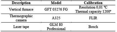

Figure 3: Numbering of internal thermocouples

Figure 4: Numbering of external thermocouples
2.4. Instrumentation
Table 2 presents the equipment used during the tests.
The internal (face of the sample exposed to fire) and external thermocouples (face of the sample not exposed to fire) are type K with diameters of 4 mm and 2 mm, respectively. Fig. 3 and Fig. 4 illustrate the positions of the thermocouples.
2.5. Evaluation criteria
For the analysis of both systems, it was evaluated the parameters of integrity, thermal insulation and structural stability, as defined [14-17] to check the fire resistance of structural walls.
The analysis of the thermal insulation is made by the thermocouples measurements in the surface not exposed to fire of the sample. In order to be thermal insulated, the maximum rise of temperature must be less or equal to 180°C in each thermocouple or 140°C on the average of all the thermocouples, whichever occurs first, adding the initial temperature of the trials [14,16,17].
The cracks found in the samples during the test are not allowed to release hot gases through its openings. The integrity is verified with a dry cotton wool pad positioned on the crack for 10 seconds, which can not inflame during the exposure, as defines [14-16]. Cracks that have not caused the inflammation of cotton wool pad were disregarded in this study, as it does not compromise the integrity parameter. To assist the identification of the cracks during the tests, a thermographic camera was used on the surface not exposed to fire.
The structural stability was verified by the horizontal deformations developed during the test, which was measured using a laser tape pointed to the center of the not exposed surface. The system was subjected to the action of a uniformly distributed load of 15kN/m, simulating a slab action load. According [14], the fire resistance time of the sample corresponds to 80% of the time period in which the element was charged and subjected to the test. Regarding the overall deformation of the load-bearing wall system, the standard states that it can not be excessive, admitting a maximum deformation of 1/30 of the span.
3. Results and discussion
3.1. Thermal insulation
The temperatures recorded in the sample "A" and Sample "B" are presented in Fig. 5 and Fig. 6, respectively.
Manifestations occurring during the test are presented Table 3.

Figure 5: Specimen ‘A’ external surface temperature - Standard (ST) plasterboard.

Figure 6: Specimen ‘B’ external surface temperature - Fire Resistant (FR) plasterboard.
The ambient temperature at the test beginning was 24.5°C and in turn the test limit is 164.5°C for the average temperature of five external thermocouple and 204.5°C for each thermocouple (thermal insulation).
The sample “A” test lasted 51.5 minutes, whereas the sample “B” lasted 62.0 minutes when the tests were finished. However, the average temperature of the five external thermocouple has not reached 164.5°C in both cases, or any individual thermocouple temperature reached 204.5°C. Therefore, the sample with fire resistant plasterboard had test duration 10.5 minutes, or 20.3%, higher than the sample with standard plasterboards.
According to the pictures and temperature graphs presented on Table 3, the samples had a similar behavior up to 40 minutes of test. The wall using the standard plasterboards (sample “A”) had initially a heat concentration at the joints, being later distributed throughout the system’s surface. The same occurred with the sample with fire resistant plasterboards (sample 'B'), which, however, presented a better performance for 10.5 minutes when compared to sample “A”.
In both cases, it was noted that the metal bolts are the first elements to present an abrupt heating. It was evident that its protection, or substitution by insulating material, can contribute to the thermal insulation of wall systems using plasterboards. The bolts and joints might be considered a weak point of this kind of system.
3.2. Integrity
After 45 minutes from the beginning of the test, it was noticed a vertical crack between two cement boards (external) on sample “A” (Fig. 7). At the same moment, the cotton wool pad test was performed. With the crack propagation, the test was repeated at 51.5 minutes and, at this occasion, the hot gases expelled caused the cotton wool pad inflammation, characterizing the system’s loss of integrity.
In the test of sample “B”, vertical cracks were identified between boards (at the joints) 50.0 minutes after the beginning of the test (Fig. 8). However, trhough the cotton wool pad test the sample still maintains its integrity. After 62 minutes of testing, the action of the hot gases produced by this opening has passed to compromise system’s integrity and the test was finished.
Source: The authors.Table 3: Temperature evolution at the unexposed spicemen’s surface

Note that the joints have proved to be the weakest point of the system, independently from the type of plasterboard used. For this reason, it is emphasized the importance of ensuring the fire resistance properties in all components of the system, not only at the plasterboards, as well as its joints.

Figure 7: Loss of integrity moment of (a) sample “A” and (b) sample “B”.

Figure 8: Deformation versus time.
3.3. Structural stability
Fig. 8 presents the evolution of measured deformations during both tests.
Since the exposed span length was 2500.0mm, the deformation limit is 83.3mm. For both samples, the deformation was very similar up to 30.0 minutes of test and less than 10.0mm. From the 30.0 minutes, sample “A” presented higher total deformation, leading to a loss structural stability. However, the deformations did not compromise the use of both samples, even though sample “A” reached 80.0mm at 50.0 minutes of testing.
4. Conclusion
It was concluded that the samples with fire-resistant plasterboard type presented a better fire performance when compared to the standard plasterboard type for all the analyzed parameters: thermal insulation, integrity and structural stability. The sample with fire-resistant plasterboards had test duration of 10.5 minutes longer than the standard type, or 20.3% higher than the sample with standard plasterboards, presenting the efficiency of using this type of material. From the 30.0 minutes, sample “A” presented higher total deformation, probably due to the higher increase of temperature on the external surface, leading to a loss structural stability. After 45 minutes from the beginning of the test, it was noticed a vertical crack between two cement boards on sample “A”, instead sample “B”, 50 minutes. In both cases, the joints between panels and bolts were critical in their behavior during the fire exposure, being responsible for the loss of integrity due the passage of gases. Therefore, attention should be taken to the thermal protection of these elements in order to promote a greater fire safety of structural LSF systems.
References
Referencias
International Organization for Standardization (ISO). ISO 834-1: Fire-resistance tests - Elements of building construction - Part 1: General requirements Genebra, 2014.
Veljkovic, M. and Johansson, B., Light steel framing for residential buildings. Thin-Walled Structures, 44(12), pp. 1272-1279, 2007. DOI: 10.1016/j.tws.2007.01.006.
Lorenzi, L.S., Análise crítica e proposições de avanços nas metodologias de ensaios experimentais de desempenho à luz da ABNT NBR 15575 (2013) para edificações habitacionais de interesse social térreas. [s.l.] Universidade Federal do Rio Grande do Sul, 2013.
Okamoto, P.S. e Melhado, S.B., A norma brasileira de desempenho e o processo de projeto de empreendimentos residenciais. Maceió: XV ENTAC, 2014
ABNT. Associação Brasileira de Normas Técnicas. NBR. 15575: Edificações Habitacionais – Desempenho. Rio de Janeiro, 2013.
International Organization for Standardization (ISO). ISO 6241: Performance standards in building - Principles for their preparation and factors to be considered. Genebra, 1984.
Sorgatto, M.J. et al., Análise do procedimento de simulação da NBR 15575 para avaliação do desempenho térmico de edificações residenciais. Ambiente Construido, 14(4), pp. 83-101, 2014.
Guo, Q. et al., Probabilistic evaluation of structural fire resistance. Fire Technology, 49(3), pp. 793-811, 2013. DOI: 10.1007/s 10 694-012-0293-6
Gunalan, S. and Mahendran, M., Finite element modelling of load bearing cold-formed steel wall systems under fire conditions. Engineering Structures, 56, pp. 1007-1027, 2013. DOI: 10.1016/j.engstruct.2013.06.022
Kodur, V.K.R. and Sultan, M.A., Factors influencing fire resistance of load-bearing steel stud walls. Fire Technology, 42(1), pp. 5-26, 2006 DOI: 10.1007/s10694-005-3730-y
Alfawakhiri, F. Sultan, M.A. and Mackinnon, D.H., Fire resistance of loadbearing steel-stud walls protected with gypsum board: A review, Fire Technology, 35(49, pp. 308-335, 1999. DOI: 10.1023/A:1015401029995
Gomes, A.P., de Souza, H.A. and Tribess, A., Impact of thermal bridging on the performance of buildings using Light Steel Framing in Brazil. Applied Thermal Engineering, 52(1), pp. 84-89, 2013. DOI: 10.1016/j.applthermaleng.2012.11.015
Gunalan, S. and Mahendran, M., Development of improved fire design rules for cold-formed steel wall systems. Journal of Constructional Steel Research, 88, pP. 339-362, 2013. DOI: 10.1016/j.jcsr.2013.05.021
ABNT. Associação Brasileira de Normas Técnicas. NBR. 5628: Componentes construtivos – Determinação da resistência ao fogo. Rio de Janeiro, 1980.
Japanese Standard Association (JIS). JIS A 1304: Method of fire resistance test for strucutral parts of buildings. Tóquio, 1994.
Standards Association of Australia. AS 1530.1: Methods for fire test to building materials, components and structures. Camberra, 1994.
British Standard. BS 476. Fire tests on building materials and structure. London, 1953.
Cadorin, J.F., Comportment fire models for structural engineering. Thesys. Université de Liége. Liége, 2003.
Cómo citar
IEEE
ACM
ACS
APA
ABNT
Chicago
Harvard
MLA
Turabian
Vancouver
Descargar cita
CrossRef Cited-by
1. Uziel Cavalcanti de Medeiros Quinino, Roberto Christ, Bernardo Fonseca Tutikian, Luis Carlos Pinto da Silva. (2022). Statistical Modeling of Compressive Strength of Hybrid Fiber-Reinforced Concrete—HFRC. Fibers, 10(8), p.64. https://doi.org/10.3390/fib10080064.
2. Marian Sabău, Claudia Ines Ayala Rueda, Jose Fernando Salas Barraza, Jholman Elifás Núñez Vivas, César Antonio Cardona Almeida. (2018). The incidence of alternative minimum load values in masonry partition and lightweight partition systems with a cost analysis in Barranquilla, Colombia. Case Studies in Construction Materials, 9, p.e00194. https://doi.org/10.1016/j.cscm.2018.e00194.
3. Ruiyi Tang, Denvid Lau, Cheuk Lun Chow. (2026). Evaluating fire risk in double-skin green façades under external wind conditions: A sustainable high-rise design. Applied Thermal Engineering, 295, p.130565. https://doi.org/10.1016/j.applthermaleng.2026.130565.
4. Yonny Martínez López, Juarez Benigno Paes, Emilio Martínez Rodríguez. (2018). Propiedades ignífugas de tableros de madera plástica producidos con diferentes especies forestales y termoplásticos reciclados. Madera y Bosques, 24(2) https://doi.org/10.21829/myb.2018.2421495.
5. Rodrigo Brito-Peña, Daniel Villa-Enderica, Esteban Zalamea-León. (2022). Análisis comparativo de confort térmico de vivienda unifamiliar en LSF frente a mampostería. Ingenius, (28), p.100. https://doi.org/10.17163/ings.n28.2022.10.
6. Leonardo Torres, Carlos Couto, Paulo Vila Real, Paulo Piloto. (2023). Numerical study of the fire behaviour of external walls in light steel framing. Fire Safety Journal, 141, p.103946. https://doi.org/10.1016/j.firesaf.2023.103946.
7. Andrey Shukhardin, Marina Gravit, Ivan Dmitriev, Gleb Nefedov, Tatiana Nazmeeva. (2020). International Scientific Conference Energy Management of Municipal Facilities and Sustainable Energy Technologies EMMFT 2018. Advances in Intelligent Systems and Computing. 982, p.836. https://doi.org/10.1007/978-3-030-19756-8_80.
8. Parisa Samiee, Shirin Esmaeili Niari, Elham Ghandi. (2021). Fire performance of cold-formed steel shear wall with different steel grade and thicknesses. Structures, 29, p.751. https://doi.org/10.1016/j.istruc.2020.11.073.
9. Giovanna Menegussi Portela, Fernanda Pacheco, Hinoel Zamis Ehrenbring, Roberto Christ, Bernardo Tutikian, Mauricio Mancio. (2025). Effects of Different Coatings on Concrete Elements Due to Chloride Ion Penetration. Coatings, 15(1), p.46. https://doi.org/10.3390/coatings15010046.
Dimensions
PlumX
Visitas a la página del resumen del artículo
Descargas
Licencia
Derechos de autor 2017 DYNA

Esta obra está bajo una licencia internacional Creative Commons Atribución-NoComercial-SinDerivadas 4.0.
El autor o autores de un artículo aceptado para publicación en cualquiera de las revistas editadas por la facultad de Minas cederán la totalidad de los derechos patrimoniales a la Universidad Nacional de Colombia de manera gratuita, dentro de los cuáles se incluyen: el derecho a editar, publicar, reproducir y distribuir tanto en medios impresos como digitales, además de incluir en artículo en índices internacionales y/o bases de datos, de igual manera, se faculta a la editorial para utilizar las imágenes, tablas y/o cualquier material gráfico presentado en el artículo para el diseño de carátulas o posters de la misma revista.