Validación de una plataforma basada en sensores inerciales para adquirir información cinemática de estimación del ángulo articular humano
Validation of an inertial sensor-based platform to acquire kinematic information for human joint angle estimation
DOI:
https://doi.org/10.15446/dyna.v83n197.50564Keywords:
captura de movimiento, señales biomecánicas, sensores inerciales, potenciómetro, extremidad superior, telerehabilitación (es)Motion capture, biomechanical signals, inertial sensors, potentiometer, upper limb, telerehabilitation (en)
captura de movimiento; señales biomecánicas; sensores inerciales; potenciómetro; extremidad superior; telerehabilitación
DOI: https://doi.org/10.15446/dyna.v83n197.50564
Validation of an inertial sensor-based platform to acquire kinematic information for human joint angle estimation
Validación de una plataforma basada en sensores inerciales para adquirir información cinemática de estimación del ángulo articular humano
Mauro Callejas-Cuervo ab, Andrés Felipe Ruíz-Olaya c & Rafael M. Gutiérrez b
a Facultad de Ingeniería, Universidad Pedagógica y Tecnológica de
Colombia, Tunja, Colombia. mauro.callejas@uptc.edu.co
b Doctorado en Ciencia Aplicada, Universidad Antonio Nariño, Bogotá,
Colombia. Rafael.gutierrez@uan.edu.co
c Facultad de Ingeniería Electrónica y Biomédica, Universidad
Antonio Nariño, Bogotá, Colombia. andresru@uan.edu.co
Received: May 11th, 2015. Received in revised form: January 17th, 2016. Accepted: May 5th, 2016.
This work is licensed under a Creative Commons Attribution-NonCommercial-NoDerivatives 4.0 International License.
Abstract
This paper
shows the results of a set of experiments aimed t at calibrating and validating
an inertial sensor-based motion capture system that is used to capture and
analyze the elbow joint flexion/extension motion. An experimental platform was
constructed that provides accurate angular position information for reference
purposes. Results obtained have an average error of 2.14 degrees when the arm
is guided by a servomotor that rotates at 1 radian per second. The system also
has an RMSE of 3.3, 4.9, 6.4 and 7.7 degrees for speeds of 2, 3, 4 and 5
radians per second respectively. Results show that the errors are
acceptable to use a kinematic
information capture platform en with inertial sensors that is focused on
monitoring the recovery of the motor function in the upper limbs through physical
therapy.
Keywords: Motion capture, biomechanical signals, inertial sensors, potentiometer, upper limb, telerehabilitation.
Resumen
El artículo presenta los resultados de una serie
de experimentos para calibrar y validar un sistema de captura de información
cinemática asociado al movimiento de flexión/extensión de la articulación del
codo, con sensores inerciales, para lo cual se construyó una plataforma con un
potenciómetro de precisión usado como referencia de posición angular. Los
resultados muestran que los datos generados por el sistema presentan un
promedio de error de 2.14 grados cuando el brazo guiado por el servomotor
funciona a una velocidad de 1 radian por segundo. El sistema también tiene un
RMSE de 3,3, 4,9, 6,4 y 7,7 grados para velocidades de 2, 3, 4 y 5 radianes por
segundo, respectivamente. Los resultados muestran que los errores son aceptables
para utilizar una plataforma de captura de información cinemática con sensores
inerciales, orientada a controlar la recuperación de la función motora en los
miembros superiores través de la terapia física.
Palabras clave: captura de movimiento, señales biomecánicas, sensores inerciales, potenciómetro, extremidad superior, telerehabilitación.
1. Introduction
The motion capturing system to measure flexion/extension, pronation/supination and abduction/adduction through the use of inertial sensors [1-2] that adhere to body segments is a broad field of research. It is found in topics such as: motion analysis [3-5]; active videogame development [6-7]; high performance athlete analysis [8-10]; physical rehabilitation on human beings [11-13]; among others. This shows how important it is to analyze locomotive and manipulative behavior as well as to identify strategies for their improvement. In spite of technological advances there are a restricted number of systems that are able to make accurate, quantitative and low-cost calculations of the angle value between the different body segments or joints.
This work shows the outcomes from a validation process of a motion capture system that is based on inertial sensors. The system allows the angle of any upper limb joint to be estimated. The validation experiments have been guided in order to obtain the flexion/extension angle from the elbow.
To calibrate the motion capture system, an experimental platform has been implemented that provides reference information on the angle between two mechanical segments: one fixed segment and one mobile segment. A precision potentiometer provides information on the reference angle. The experiments were made by mounting the inertial sensors onto segments in the experimental platform. The angle estimate is carried out by merging information from inertial sensors (a 3-axis accelerometer and a 3-axis gyroscope). The angle has been validated for the following different angular velocities: 1, 2, 3, 4 and 5 rad/s.
The structure of this article is the following: section 2 includes an introduction to orientation kinematics. Section 3 presents the experimental methods that include the construction of a test platform, programming and adjusting of the data capture software, reference system calibration, and data acquirement and outcomes analysis. Section 4 presents the results, and finally the conclusions are presented.
2. Orientation kinematics
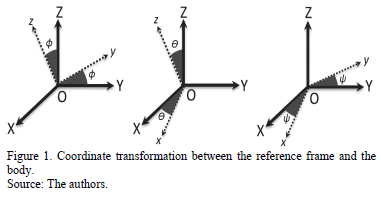
Within a joint angle estimation context, orientation kinematics relates to the calculation of the relative orientation of a body relative to a global coordinate system. It is useful to attach a coordinate system to the body frame as well as another one to the reference when both, the reference and the body frames, have the same fixed origin. Fig. 1 presents a system with two coordinate systems: the body frame (Oxyz) and the reference frame (OXYZ).
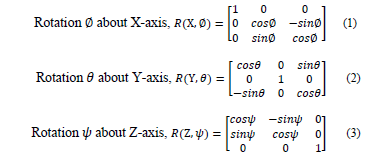
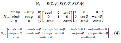
Taking X,Y, Z as a reference coordinate system, and x, y, z as a body coordinate system, the rotation matrices are given by eq. (1) - (4):
3. Experimental methods
The following subsections are the stages used to develop the calibration processes as well as the validation of the inertial platform for human motion capture and analysis.
3.1. Experimental platform construction
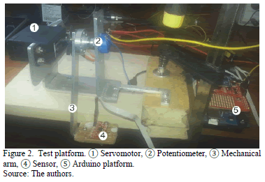
The tests platform is a reliable and steady environment that allows data capture instead of reference. This platform is composed of an articulate segment together with a servomotor that provides movement and a high precision potentiometer, such as the one in Fig. 2.
Moreover, the platform integrates a control and processing unit, in this case, a microcontroller within an Arduino's board. The chosen sensor for application is an MPU-9150 from Invensense [15], which has 9 degrees of freedom and combines a three axis gyroscope, a three axis accelerometer and a three axis magnetometer; a Xbee wireless communication system that connects Arduino with the graphic interface from the developed system, which can be accessed from different devices (PC, Tablet, Smartphone and others); a 6v-2600mAh battery as a power supply. The MPU9150 sensor provides digital information through an I2C communication. Finally, the connection of the wireless communication modules is made through an Xbee shield for Arduino and a RF Xbee module.
3.2. Software/firmware for sensors data capture
After a test environment, it is necessary to program the data acquirement software. In this stage, some computational algorithms are created, proved and adjusted, and these are implemented on the capture system, the purpose of which is to collect, process, and distribute data from the whole motion capture system.
The firmware within the Arduino's board microcontroller is responsible for generating the communication link between sensors and users or data processing software, as well as containing the necessary functions to carry out the corresponding reading, setup, and processing of the information from the inertial sensors that are connected to it. Inside the developed software, there are several libraries containing basic functions that collect information from sensors in addition to mathematical algorithms that process the collected data. The following libraries are structured as follows [16]:
MPU9150 Library: This part of the firmware contains the functions necessary to execute the fusion of the inertial sensor's nine axis, through data obtention,the correlation of magnitudes, their variables and the implementation of calculation algorithms that deliver as results values in different units of measurement (quaternions, total and axis Euler angle, differential angles and raw values from the sensor).
Calibration Library: This contains the code related to the magnetometer and accelerometer calibration (the gyroscope does not require calibration). It also disposes of specialized algorithms for necessary specific data collection during the calibration, for example the auto select of the most relevant and accurate information that sensor can give.
Motion Driver: This contains selected and modified files from Embedded SDK v5.1 provided by InvenSense, and it is necessary to manage the sensor hardware.
I2CDev: This contains communication utilities between hardware and software through I2C protocol. It was originally created by Jeff Rowberg with an open source license. It has been slightly modified for its use in this application.
DueFlash: EEPROM library for AVR Arduinos. In this case, it is used to permanently write the outcomes of the calibration within EEPROM memory into the Arduino's board microcontroller.
Thus, there are tools to suitably capture and visualize data to later undertake the respective calculation and analysis.
3.3. Experimental platform calibration
The reference system used is based on a precision potentiometer, which is adjusted with manual tools that provide the angle information for different angular positions.
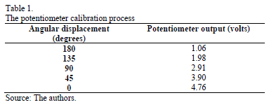
Maximum and minimum values of the potentiometer are read in order to find out the range of operation and correlate this with the information provided by a protractor. These values are computed by magnitude in voltage to correspond to an image in degrees. This allows a direct comparison between the potentiometer and the sensor information.
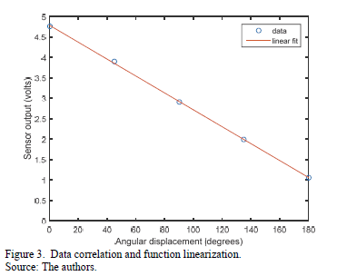
Several data collections of the mechanical segment motion were made in order of establish the correlation between voltage value and the angular displacement by the potentiometer. The outcome of the comparison with angles (180º, 135º, 90º, 45º and 0º) can be seen in Table 1.
3.4. Data acquisition
In this stage, hardware and software are merged to collect necessary information from the experiments by taking into account different factors such as synchronization and reliability from the data recorded on different devices in the tests.
The conditioned potentiometer signal provides an analog voltage that is proportional to the angular displacement received through mechanical arm.
Information provided by the inertial sensor and magnetometer, relates to the transformation process of signals from acceleration, angular velocity and the magnetic field.
Information provided by the angular sensor relates to the transformation process of signals from the inertial sensor (acceleration, angular velocity and magnetic field). This angular information (Euler angles) was computed from equations (1) to (3) and corresponds to elbow joint flexion-extension. Further movements can be calculated from the rotation matrix in equation (4).
4. Results and Discussion
The results are carried out in four steps that involve the statistical analysis of the data, the linearization equation, data collection graphics generation, and quantitative analysis of variables.
4.1. Data statistical analysis
From the data acquired, batches of information were processed in a specialized software (OriginLab Demo) [17], thus, its intercept, percentage deviation, pendant, statistical correlation and median were calculated. This information allowed for an arithmetic linearization that corrects bugs from all the processed values by means of averaging. For the purpose of complementing the analysis, data correlation and function linearization were graphed, thus it was corroborated that the method used is correct, and the system modeling to a linear equation was simplified, as can be seen in Fig. 3.
4.2. Equation linearization
By using linear regression, the best-fitting straight line through the points was found. The equation for the line in Fig. 3 is:

Equation (5) linearly correlates to the value of the potentiometer and shows the value in degrees, which represents the reference.
4.3. Graphical outcomes
Once data batches collected in test platforms were converted and adjusted through the mathematical modeling described above, their graphics were created in order to ease the theoretical analysis and provide the most relevant information about tests.
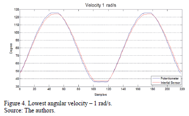
With an angular velocity of 1 rad/s, a high performance of the sensor can be seen in terms of the potentiometer. This is the system reference, as can be seen in Fig. 4.
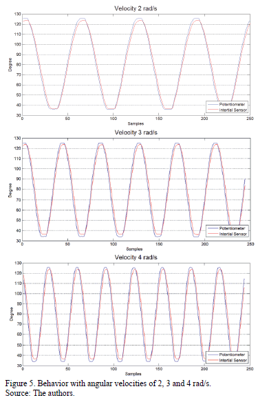
A 1 rad/s velocity is of interest for this research as the upper-limb motion of a human body is usually placed within this velocity range. However, some tests were made with velocities of 2, 3 and 4 rad/s (Fig. 5), which presented similar behavior to the motion tracing but with an increase in the bug by the inertial sensor due to drift bias from the gyroscope [18-19] and white noise added by magnetic materials to the magnetometer signals [20].
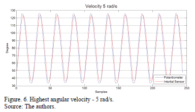
Finally, the behavior of the system was analyzed with a higher velocity of 5 rad/s (see Fig. 6) supposing an abrupt movement infrequent in human upper limb biomechanics. However, from a technical point of view, it is interesting to analyze this in order to determine the effective response of the system, even in extreme cases or when some kind of abuse in its correct use can be presented.
Furthermore, graphic and mathematical information can be merged in real time to determine other system behaviors, such as parasitic noises, deviations in measurements or even sensor calibration according to the variables imposed by the environment.
4.4. Quantitative analysis of variables
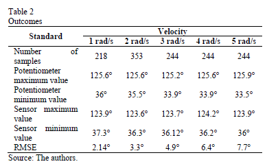
The root mean square error (RMSE) was used to quantify the difference of the value of the angles between the reference information (potentiometer) and the estimate using the inertial sensor. This can be seen in eq. (6) and (7).

where k represents the number of samples taken with both systems and n, represents a sample in a time slot.
Table 2 summarizes the collected data using the tests platform that allowed the information and the performance in both systems in different circumstances to be characterized.
5. Conclusions
According to the results obtained in the tests, and taking into account their exactness in terms of the reference system, it becomes possible to identify that the system provides high efficiency in normal movements (from 1 and 2 rad/s), showing stability and reliability. However, projecting the implementation of a filter or estimator is necessary as it allows for the drift problem of the inertial sensors to be controlled, as well as the removal of white noise added to the signal during capture.
The results obtained through calibration and validationare sufficiently accurate, in terms of the data generated by an MPU-9150 sensor, to continue developing the capture and biomechanical data analysis platform that is used for telerehabilitation purposes. This is proposed in [5]. Also, the technology used is ergonomically enhanced, accurate, and has an easy handling option for any technical medical user.
References
[1] Shaeffer, D.K., MEMS Inertial Sensors: A tutorial overview. IEEE Commun. Mag., 51(54), pp. 100-109, 2013. DOI: 10.1109/MCOM.2013.6495768.
[2] Yazdi, N., Ayazi, F. and Najafi., Micromachined inertial sensors. Proceedings of the IEEE. 86(8), pp. 1640-1659, 1998. DOI: 10.1109/5.704269.
[3] Choudhury, T.T., Rahman, M.M., Khorshidtalab, A. and Khan, M.R., Modeling of human arm movement: A study on daily movement. Fifth Int. Conf. Comput. Intell. Model. Simul, 2013. pp. 63-68. DOI: 10.1109/CIMSim.2013.19.
[4] Tao, G., Huang, Z., Sun, Y., Yao, S. and Wu, J., Biomechanical model-based multi-sensor motion estimation. IEEE Sensors Appl. Symp. Proc., 2013. pp. 156-166. DOI: 10.1109/SAS.2013.6493577.
[5] Callejas-Cuervo, M., Ruíz-Olaya, A.F. and Gutierrez, R., Biomechanical motion capture methods focused on tele-physiotherapy. Pan American Health Care Exchanges, 2013. pp. 1-6. DOI: 10.1109/SAS.2013.6493577.
[6] Chiang, I.-T., Tsai, J.-C. and Chen, S.-T., Using Xbox 360 kinect games on enhancing visual performance skills on institutionalized older adults with wheelchairs. IEEE Fourth Int. Conf. Digit. Game Intell. Toy Enhanc. Learn, 2012. pp. 263-267. DOI: 10.1109/DIGITEL.2012.69.
[7] Lange, B., Koenig, S., McConnell, E., Chang, C.-Y., Juang, R., Suma, E., Bolas, M. and Rizzo, A., Interactive game-based rehabilitation using the Microsoft Kinect. IEEE Virtual Real, 2012. pp. 171-172. DOI: 10.1109/VR.2012.6180935.
[8] Coyte, J.L., Stirling, D., Ros, M. and Gray, A., Displacement profile estimation using low cost inertial motion sensors with applications to sporting and rehabilitation exercises. IEEE/ASME Int. Conf. Adv. Intell. Mechatronics, 2013. pp. 1290-1295. DOI: 10.1109/AIM.2013.6584272.
[9] Charry, E., Hu, W., Umer, M., Ronchi, A. and Taylor, S., Study on estimation of peak ground reaction forces using tibial accelerations in running. IEEE Eighth Int. Conf. Intell. Sensors, Sens. Networks Inf. Process., 2013. pp. 288-293. DOI: 10.1109/ISSNIP.2013.6529804.
[10] Jung, P.-G., Lim, G. and Kong, K., A mobile motion capture system based on inertial sensors and smart shoes. IEEE Int. Conf. Robot. Autom., 2013. pp. 692-697. DOI: 10.1109/ICRA.2013.6630648.
[11] Zhang, S., Naghdy, F., Stirling, D. and Gray, A., Ankle injury assessment using inertial 3D data. IEEE/ASME International Conference on Advanced Intelligent Mechatronics (AIM), 2013. pp. 810-815. DOI: 10.1109/AIM.2013.6584193.
[12] Bruckner, H.-P., Nowosielski, R., Kluge, H. and Blume, H., Mobile and wireless inertial sensor platform for motion capturing in stroke rehabilitation sessions. 5th IEEE Int. Work. Adv. Sensors Interfaces IWASI, 2013. pp. 14-19. DOI: 10.1109/IWASI.2013.6576085.
[13] Zhang, Z.-Q., Ji, L.-Y., Huang, Z.-P. and Wu, J.-K., Adaptive information fusion for human upper limb movement estimation. IEEE Trans. Syst. Man, Cybern. - Part A Syst. Humans, 42(5), pp. 1100-1108, 2012. DOI: 10.1109/TSMCA.2012.2189876.
[14] Álvarez, D., Alvarez, J.C., González, R.C. and López, A.M., Upper limb joint angle measurement in occupational health, Comput. Methods Biomech. Biomed. Engin. pp. 1-12. 2015. DOI: 10.1080/10255842.2014.997718
[15] Invensence. Technology Motion, [online]. [Date of reference: June 2015]. Available at: http://www.invensense.com/technology/motion/
[16] Arduino, Libraries of programing, [online]. [Date of reference: June 2015]. Available at: http://playground.arduino.cc/Main/MPU-9150
[17] OriginaLab. Software Demo, [online]. [Date of reference: June 2015]. Available at: http://www.originlab.com/demodownload.aspx
[18] Olivares, A., Olivares, G., Mula, F., Górriz, J.M. and Ramírez, J., Wagyromag: Wireless sensor network for monitoring and processing human body movement in healthcare applications. J. Syst. Archit., 57(10), pp. 905-915, 2011. DOI: 10.1016/j.sysarc.2011.04.001.
[19] Vaccaro, R. and Zaki, A., Statistical modeling of rate gyros. IEEE Trans. Instrum. Meas., 61(3), pp. 673-684, 2012. doi: 10.1109/TIM.2011.2171609.
[20] Butta, M. and Sasada, I., Sources of noise in a magnetometer based on orthogonal fluxgate. IEEE Trans. Magn., 48(4), pp. 1508-1511, 2012. DOI: 10.1109/TMAG.2011.2173177.
M.Callejas-Cuervo, received his BSc. in System Engineering in 1997 and is currently undertaking his PhD in Applied Science, both from the Antonio Nariño University, in Bogotá, Colombia. He is also a PhD student in Energy and Process Control at Oviedo University, Spain. He received an MSc in Computer Science from the Institute of Technology in Monterrey, Mexico. He is a full-time professor in the Faculty of Engineering at the Pedagogical and Technological University of Colombia, and a member of the Software Research Group. His research interests include motion capture with inertial sensor projects in telerehabilitation and development of video game actives, as well as software engineering and business intelligence. ORCID: 0000-0001-9894-8737
A.F. Ruiz-Olaya, received his BSc. in Electronic Engineering from the University of Valle, Cali, Colombia and his PhD from Carlos III University of Madrid, Spain. He is a full-time professor in the Faculty of Electronics and Biomedical Engineering at the Antonio Nariño University, Bogotá, Colombia, institution in which he is a member of the Bioengineering Research Group. His research interests include robotics rehabilitation, multimodal human-robot interaction, bioinspired control architectures and modeling of human motor control. Currently, he is working on several projects oriented towards the development of neurorehabilitation systems to aid individuals with motor disabilities. Prof. Ruiz-Olaya is a member of IEEE. He has been author and co-author of multiple papers and has worked as reviewer of several important international journals and conferences. ORCID: 0000-0002-5883-5786
R.M. Gutierrez, received his BSc in Physics from the Universidad Nacional de Colombia, his MSc in Condensed Matter from Montreal University, Mexico, and his PhD in Applied Sciences from New York University, USA. He is Director of an Applied Science PhD Program and Head of the Complex System Research Group at the Antonio Nariño University in Bogotá, Colombia. He has also been vice director of the Scientific and Technology Development Program at the Colombian Institute for the Development of Science And Technology "Francisco José De Caldas" - Colciencias, March 2006 - March 2007 and Director of Basic Sciences on a National Program at the Colombian Institute for the Development of Science And Technology "Francisco José De Caldas" - Colciencias, October 2004 - March 2006. He is author of more than 130 indexed publications in various interdisciplinary subjects. ORCID: 0000-0001-5734-6174
How to Cite
IEEE
ACM
ACS
APA
ABNT
Chicago
Harvard
MLA
Turabian
Vancouver
Download Citation
License
Copyright (c) 2016 DYNA

This work is licensed under a Creative Commons Attribution-NonCommercial-NoDerivatives 4.0 International License.
The author of a paper accepted for publication in any of the journals published by the School of Mines will yield all the property to the National University of Colombia rights free of charge, within which include article: the right to edit, publish, reproduce and distribute both print and digital media, as well as including in an article in international indexes and / or databases, likewise, it enables the publisher to use images, tables and/or graphic material presented in Article for designing covers or posters of the magazine. By assuming the economic rights of the article, it may be reproduced partially or totally in any printed or digital media without express permission of the same.


