Publicado
Obtaining the electrical impedance phase using Wavelet transform and Fourier transform from transient signals. Part 2: practical assessment and validation
Obtención de la fase de la impedancia eléctrica usando transformada Wavelet y transformada de Fourier de señales transitorias. Parte 2: evaluación práctica y validación
DOI:
https://doi.org/10.15446/dyna.v85n205.68458Palabras clave:
continuous wavelet transform (CWT), frequency response, online supervision and control, power system transients and transformers (en)transformada Wavelet continua (CWT), respuesta en frecuencia, supervisión y control en línea, transitorios del sistema eléctrico y transformadores (es)
Descargas
Recibido: 24 de octubre de 2017; Revisión recibida: 8 de marzo de 2018; Aceptado: 9 de abril de 2018
Abstract
This article presents a practical assessment and validation of the new proposed approach based on the continuous wavelet transform (CWT) to obtain the electrical impedance phase from online transient signals for a real transformer. Besides the mathematical procedure presented in a previous paper, an electronic system was also designed and implemented, in order to inject superimposed controlled pulses to the power system (50/60 Hz) wave. The results show improved performance of the wavelet transform compared to that of the Fourier Transform, for transient signal analysis to be applied on a nonintrusive transformer monitoring approach. Particularly, this new approach proves useful in overcoming problems related to signal filtering and signal processing in an online frequency-response analysis of a transformer diagnosis.
Keywords:
continuous wavelet transform (CWT), frequency response, online supervision and control, power system transients and transformers.Resumen
Este artículo presenta la validación y evaluación práctica para la nueva propuesta presentada, basada en la Transformada Wavelet Contínua (CWT) para obtener la fase de la impedancia eléctrica de señales transitorias en línea de un transformador real. A parte del procedimiento matemático presentado en la parte 1, también se diseñó e implementó un sistema electrónico para inyectar pulsos controlados en la onda del sistema de potencia (50/60 Hz). Los resultados muestran un mejor rendimiento de la Transformada Wavelet en comparación con la transformada de Fourier, para el análisis de señales transitorias para ser aplicado en un enfoque de monitoreo de transformadores no intrusivo. En particular, este nuevo enfoque permite superar algunos problemas de filtrado y procesamiento de señales en el análisis de respuesta en frecuencia de un transformador en servicio.
Palabras clave:
transformada Wavelet continua (CWT), respuesta en frecuencia, supervisión y control en línea, transitorios del sistema eléctrico y transformadores.1. Introduction
A new theoretical method to obtain the frequency response from the online transient signals measurement (with the transformer in service) was presented in a previous paper [1-6].
This new method is based on the continuous wavelet transform (CWT), which enables improved performance compared to the traditional Fourier transform. The transient signals presented as examples in that paper came from simulations within the Alternative Transients Program (ATP). In recent years, there has been a growing interest in frequency-response analysis (FRA) with the transformer in service, since no transformer disconnection is required to conduct the test.

Figure 1: Schema of the proposed method for the measurement of the online FRA in transformers.
Testing under these conditions allows for the monitoring of the transformer and the detection of any abnormalities before they cause catastrophic failures in power grids [2,3]. Although there have been efforts and contributions to carry out the frequency response test with the transformer in service, state of the art is not mature and there is still much research to be done [4].
This paper presents the assessment and validation of the proposed method in real transformers, using the continuous wavelet transform (CWT) [1] as a powerful tool for the filtering, denoising, and processing of transient signals. As will be shown, improvement is achieved when using this new method, including non-repeatability effects and noise content in the measurements, as well as in non-periodical waveforms processing constraints.
2. Experimental set in the pilot transformer
Fig. 2 shows the experimental set in the pilot transformer carried out in the high-voltage laboratory of the Universidad del Valle [6] and Fig. 3 shows the pilot transformer. An OFF- LINE test was performed in a transformer, with high voltage winding short circuited and low winding open to obtain the transient signals. Results of voltage and current signal measurements are shown in Fig. 4 and Fig. 5, respectively.

Figure 2: Experimental set in the pilot transformer.

Figure 3: Pilot transformer.

Figure 4: Time domain voltage signal, with a 2ms window of 20.000 samples at 10M samples/s.

Figure 5: Time domain current signal, with a 2ms window of 20.000 samples at 10M samples/s.
3. Practical proposed method for carrying out the online FRA test
The proposed method to obtain the frequency response with the transformer in service (online) involves the three stages presented in the block diagram shown in Fig. 1.
3.1. Stage 1. Injection and signal measurements
An electronic circuit was designed and implemented for the injection system to inject microsecond-width controlled voltage pulses on the power wave of 60 Hz [4]. The injection system enables setting the amplitude, width, and phase of the generated pulses, by means of the circuit shown in Fig. 6, with Fig. 7 showing an example of controlled pulses on the (60 Hz) voltage signal.

Figure 6: Actual assembly of the injection system for online IFRA.

Figure 7: Controlled pulses on the (60 Hz) voltage signal used for the online IFRA method.

Figure 8: Block diagram of the filtering and signal processing of S(t).
3.2. Stage 2. Filtering, denoising, signal acquisition, and processing
The voltage and current signals were modeled according to S(t) presented in Eq. (1), which is composed of three terms. The first one represents the nature of the transformer’s condition itself and constitutes the main information we want to extract from the measurement. It is mathematically defined as a summation of N terms, where Bk are the residues and Pk the modes or poles determining the shape of the transient signal. This main information is contaminated by the background noise n(t), and the harmonic distortion h(t) coming from the fundamental power 50/60-Hz frequency component.

Once made filtering applies the CWT, it is defined as Eq. (2) [5].

Where the asterisk represents the conjugate of the complex function, f t is the transient signal itself, 𝜓(t) is the wavelet function which defines the mother wavelet in use, in which “𝜏” conducts the translation and factor, and “𝑎” provides the dilation (or scaling) factor.
In part 1, it was demonstrated that using the mother wavelet Complex Morlet yields excellent results [1]. The complex Morlet wavelet transform is defined in Eq. (3) [5-16].

Applying the wavelet transform to the transient signals of both current and voltage [10-15] in its discrete form. Eq. (4) and Eq. (5), since a measured transient is not a continuous function but a matrix of points [16-20].


With the information of the data we can get the ratio between the coefficients 𝐶 𝑉 y 𝐶 𝐼 as shown in Eq. (6) obtaining the coefficients 𝐶 𝑍 .

The impedance phase at the scale defined by “𝑎” can be obtained from the integration of Eq. (6) along the whole window time of the transient. Due to its complex nature, the integration is performed under a vector approach. The phase can be obtained by means of Eq. (7).

Where the operators “𝑅𝑒” and “𝐼𝑚” are the real part and imaginary part of the complex coefficients, respectively.
3.2. Stage 3. Assessment and validation approach
The transformer impedance, computed from online time-domain records was measured while the transformer was energized and compared with the corresponding sweep frequency- response analysis (SFRA) offline response, obtained by using frequency-response analysis equipment.
4. Experimental results
With a commercial instrument (MEGGER FRAX-101), the transformer SFRA was obtained and taken as reference, as shown in Fig. 9.
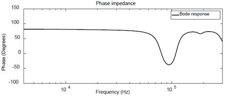
Figure 9: Transformer frequency response SFRA (reference signal).
The result with Fourier transform was obtained as shown in Fig. 10 and with Wavelet transform as shown in Fig. 11.
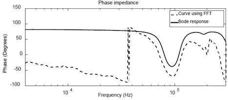
Figure 10: FFT assessments using a 2ms time window: phase frequency response.
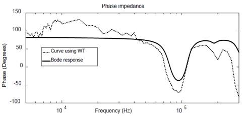
Figure 11: WT assessments using a 2ms time window: phase frequency response.
As observed in Fig. 11, WT offers a better approximation to reference, in a frequency range 4kHz to 40kHz, compared to FFT; After this, a repeatability analysis was performed, obtaining the response for the first three pulses of the time signal for WT and FFT methods, as shown in Fig. 13 and Fig. 14, respectively.

Figure 12: WT assessments using a 2ms time window: phase frequency response for three pulses.

Figure 13: FFT assessments using a 2ms time window: phase frequency response for three pulses.
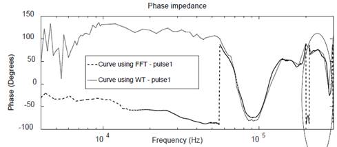
Figure 14: FT and WT assessments using a 1,5ms window of 15.000 samples at 2.5 M samples/s.: phase frequency response.
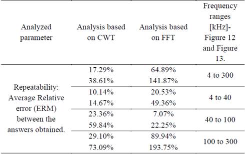
Table 1 shows the quantitative analysis, of the results obtained when using both methods.
A qualitative analysis, using the average Relative error (TERM), was made to compare the two methods, in which best results were obtained for the CWT method [19-22].
Table 1: Quantitative analysis of the curves.
Source: The authors.
To confirm the advantage in using WT, the same experimental example was used with a time window of 1,5ms and 15.000 samples, but with a sampling frequency of 2,5M samples / s.
Unlike the FFT, the WT is not altered by the changes generated shown in the part enclosed in Fig. 14, which demonstrates that the proposed method is a suitable one.
5. Conclusions
This article proposes an improved method for processing signals from time to frequency for the impedance phase. It allows overcoming the traditional Fourier Transform performance, since no periodical signals are required at all. This feature can be much more useful for engineering design and analysis because it allows working with non-periodical transient responses.
A simple example showed that, when the measurement conditions are tightened, the proposed WT based procedure performs better than the FT.
The key points in the procedure are a suitable election of the mother wavelet (Complex Morlet, in this case) and of the proposed frequency response values calculation (frequency domain) from the wavelets coefficients (time-scale domain). Thus, a correct analysis of the phase of the impedance, leads to better results for the wavelet transform, in comparison with those of the Fourier transform under both simulated and experimental conditions, which adds to the potential of WT as a suitable for the processing of transient signals.
Acknowledgments
The authors express their heartfelt thanks to the PTI S.A. Company for its support in the elaboration of this paper. They also thank COLCIENCIAS for its support for Project 54558, 2016, an approved project to access tax benefits and The Universidad del Valle for all it provided us with.
References
Referencias
Gómez-Luna, E., Cuartas-bermúdez, J. S. and Marlés-sáenz, E., Obtaining the electrical impedance phase using Wavelet transform and Fourier transform from transient signals. Part 1 : Theoretical analysis Wavelet y transformada de Fourier de señales transitorias. Parte 1: Análisis teórico DYNA vol. 84, no. 201, pp. 138–144, 2017. DOI: https://doi.org/10.15446/dyna.v84n201.58694
Krieg, T. and Napolitano, M., Techniques and experience in on-line transformer condition monitoring and fault diagnosis in ElectraNet SA. in Proc. IEEE Int. Conf. Power Syst. Technol. PowerCon Substation Maint.e Dept., 2000, vol. 2, pp. 1019–1024. DOI: 10.1109/ICPST.2000.897160
Mackenzie, E. A., Crossey, J., DePablo, A. and Ferguson, W., On-line monitoring and diagnostics for power transformers, in Proc. IEEE Int. Symp. Elect. Insul. Conf., 2010, pp. 1–5. DOI: 10.1109/ELINSL.2010.5549734
Gómez-Luna, E., Aponte, G., Gonzalez-Garcia, C. and Pleite, J., Current status and future trends in the Frequency Response Analysis (FRA) with the transformer in service, IEEE Trans. Power Del., vol. 28, no. 2, pp. 1024–1031, Apr. 2013. Research Group Gralta, Desarrollo. DOI: 10.1109/TPWRD.2012.2234141
Gómez-Luna, E., Silva, D., Aponte, G., Pleite, J. and Hinestroza, D., Obtaining the electrical impedance using wavelet transform from the time response, IEEE Transactions on Power Delivery, Vol. 28, No. 2, pp. 1242-1244, April 2013. DOI: 10.1109/TPWRD.2012.2234942
Krieg, T., and Napolitano, M., Techniques and experience in on-line transformer condition monitoring and fault diagnosis in ElectraNet SA, in Proc. IEEE Int. Conf. Power Syst. Technol. PowerCon Substation Maint.e Dept., 2000, vol. 2, pp. 1019–1024. DOI: 10.1109/ICPST.2000.897160
Gómez-Luna, E., Aponte, G. and Pleite, J., Application of Wavelet Transform to obtain the Frequency Response of a Transformer from Transient Signals – Part 2: Practical assessment and validation. IEEE Transactions on Power Delivery, Vol. 29, No. 5, pp. 2231 - 2238, October 2014. DOI: 10.1109/TPWRD.2013.2295377
Gomez-Luna, E., Obtención De La Respuesta En Frecuencia De Transformadores En Servicio a Partir De La Medida De Señales Transitorias. Tesis de Doctorado, Universidad del Valle. p. 95, 2013.
Research Group Gralta, Desarrollo de una prueba piloto para obtener la respuesta en frecuencia de un transformador en servicio, Universidad del Valle, Valle, Spain, Tech. Rep. 2653, Aug. 2012.
Yunhui, S. and Qiuqi, R., Continuous wavelet transforms, Proc. 7th Int. Conf. Signal Process. 2004. Proceedings. ICSP ’04. 2004., vol. 1, pp. 207–210, 2004. DOI: 10.1109/ICOSP.2004.1452618
Li, H., Complex Morlet Wavelet Amplitude and Phase Map Based Bearing Fault Diagnosis no. 50775219, pp. 6923–6926, 2010. DOI: 10.1109/WCICA.2010.5554232
Nieto, N. and Orozco, D., El uso de la transformada wavelet discreta en la reconstrucción de señales senosoidales, no. 38, pp. 381–386, 2008. DOI: http://dx.doi.org/10.22517/23447214.3809
Butler, K. L., Bagriyanik. M., Characterization of transients in transformers using discrete Wavelet Transformer. IEEE Transactions on Power Systems, Vol. 18, No. 2, pp. 648-656, Mayo 2003. DOI: 10.1109/TPWRS.2003.810979
Mallat, S., A Wavelet Tour of Signal Processing. A Wavelet Tour Signal Process. Third Edition. pp. 20–41, 1999.
Leigh, G. M. Fast FIR Algorithms for the Continuous Wavelet Transform From Constrained Least Squares. IEEE Transactions on Signal Processing, Vol. 61, No. 1, January 1, 2013. DOI: 10.1109/TSP.2012.2222376
Robertson, D. C., Camps, O. I., Mayer, J. S., Gish, W. B., Wavelets and electromagnetic power system transients. IEEE Transactions on Power Delivery, Vol, 11. Abril de 1996. DOI: 10.1109/61.489367
Dwivedi, U. D. and Singh, S. N., Denoising techniques with change-point approach for wavelet-based power-quality monitoring. IEEE Trans. Power Deliv., vol. 24, no. 3, pp. 1719–1727, 2009. DOI: 10.1109/TPWRD.2009.2022665
Gomez-Luna, E., Aponte Mayor, G., Pleite Guerra, J., Silva Salcedo, D. F. and Hinestroza Gutierrez, D., Application of wavelet transform to obtain the frequency response of a transformer from transient signals-part 1: Theoretical analysis. IEEE Trans. Power Deliv., vol. 28, no. 3, pp. 1709–1714, 2013. DOI: 10.1109/TPWRD.2013.2262058
Pleite, J., Olias, E., Barrado, a., Lazaro, a. and Vazquez, J., Transformer modeling for FRA techniques. IEEE/PES Transm. Distrib. Conf. Exhib., vol. 1, pp. 317–321, 2002. DOI: 10.1109/TDC.2002.1178342
Cortés, J. A., Cano-Garzón, H. B. and Chaves, J. A., Del análisis de Fourier a las Wavelets - Transformada continua wavelet (CWT). Sci. Tech., vol. XIII, no. 37, pp. 133–138, 2007. DOI: http://dx.doi.org/10.22517/23447214.4017
Montoya, F. G., Manzano-Agugliaro, F., López, J. G. and ALGUACIL, P. S., Técnicas De Investigación En Calidad Eléctrica: Ventajas E Inconvenientes. Dyna, vol. 79, no. 173, pp. 66–74, 2012.
Gómez-Luna, E., Aponte, G. and Pleite, J., Sistema de obtención de la respuesta en frecuencia de máquinas eléctricas, Madrid España Patente ES-2534954_B1, February 09, 2016.
Cómo citar
IEEE
ACM
ACS
APA
ABNT
Chicago
Harvard
MLA
Turabian
Vancouver
Descargar cita
CrossRef Cited-by
1. Jie Jin, Zhou Su, Yuehua Wei, Shi Lin. (2020). Online Estimation of Membrane Water Content in Vehicular PEMFC by Complex Morlet Wavelet Transformations. SAE International Journal of Advances and Current Practices in Mobility, 3(1), p.598. https://doi.org/10.4271/2020-01-2255.
Dimensions
PlumX
- Citations
- CrossRef - Citation Indexes: 1
- Scopus - Citation Indexes: 2
- Usage
- SciELO - Full Text Views: 279
- SciELO - Abstract Views: 36
- Captures
- Mendeley - Readers: 6
Visitas a la página del resumen del artículo
Descargas
Licencia
Derechos de autor 2018 DYNA

Esta obra está bajo una licencia internacional Creative Commons Atribución-NoComercial-SinDerivadas 4.0.
El autor o autores de un artículo aceptado para publicación en cualquiera de las revistas editadas por la facultad de Minas cederán la totalidad de los derechos patrimoniales a la Universidad Nacional de Colombia de manera gratuita, dentro de los cuáles se incluyen: el derecho a editar, publicar, reproducir y distribuir tanto en medios impresos como digitales, además de incluir en artículo en índices internacionales y/o bases de datos, de igual manera, se faculta a la editorial para utilizar las imágenes, tablas y/o cualquier material gráfico presentado en el artículo para el diseño de carátulas o posters de la misma revista.