Published
Research on Test-bench for Sonic Logging Tool
DOI:
https://doi.org/10.15446/esrj.v20n1.54141Keywords:
Sonic logging tool, test-bench, embedded controlling board, modularization, layered architecture. (en)In this paper, the test-bench for sonic logging tool is proposed and designed to realize automatic calibration and testing of the sonic logging tool. The test-bench System consists of Host Computer, Embedded Controlling Board, and functional boards. The Host Computer serves as the Human Machine Interface (HMI) and processes uploaded data. The software running on Host Computer is designed on VC++, which is developed based on multithreading, Dynamic Linkable Library (DLL) and Multiple Document Interface (MDI) techniques. The Embedded Controlling Board uses ARM7 as the microcontroller and communicates with Host Computer via Ethernet. The Embedded Controlling Board software is realized based on embedded uclinux operating system with a layered architecture. The functional boards are designed based on Field Programmable Gate Array (FPGA) and provide test interfaces for the logging tool. The functional board software is divided into independent sub-modules that can repeatedly be used by various functional boards and then integrated those sub-modules in the top layer. With the layered architecture and modularized design, the software system is highly reliable and extensible. With the help of designed system, a test has been conducted quickly and successfully on the electronic receiving cabin of the sonic logging tool. It demonstrated that the system could greatly improve the production efficiency of the sonic logging tool.
https://doi.org/10.15446/esrj.v20n1.54140
Research on Test-bench for Sonic Logging Tool
Xianping Liu, Xiaodong Ju, Wenxiao Qiao, Junqiang Lu, Baiyong Men, Kai Zhang, Yongchao Yao
State Key Laboratory of Petroleum Resources and Prospecting, China University of Petroleum, Beijing 102249, P. R. China
Email: 2005xinchen2006@163.com
Record
Manuscript received: 12/11/2015 Accepted for publication: 05/02/2016
How to cite item
Liu, X., Ju, X., Qiao, W., Lu, J., Men, B., Zhang, K., & Yao, Y. (2016). Research on Test-bench for Sonic Logging Tool. Earth Sciences Research Journal, 20(1), K1- K4. doi: https://doi.org/10.15446/esrj.v20n1.54140
ABSTRACT
In this paper, the test-bench for sonic logging tool is proposed and designed to realize automatic calibration and testing of the sonic logging tool. The test-bench System consists of Host Computer, Embedded Controlling Board, and functional boards. The Host Computer serves as the Human Machine Interface (HMI) and processes uploaded data. The software running on Host Computer is designed on VC++, which is developed based on multithreading, Dynamic Linkable Library (DLL) and Multiple Document Interface (MDI) techniques. The Embedded Controlling Board uses ARM7 as the microcontroller and communicates with Host Computer via Ethernet. The Embedded Controlling Board software is realized based on embedded uclinux operating system with a layered architecture. The functional boards are designed based on Field Programmable Gate Array (FPGA) and provide test interfaces for the logging tool. The functional board software is divided into independent sub-modules that can repeatedly be used by various functional boards and then integrated those sub-modules in the top layer. With the layered architecture and modularized design, the software system is highly reliable and extensible. With the help of designed system, a test has been conducted quickly and successfully on the electronic receiving cabin of the sonic logging tool. It demonstrated that the system could greatly improve the production efficiency of the sonic logging tool.
Keywords: Sonic logging tool, test-bench, embedded controlling board, modularization, layered architecture.
Introduction
The test equipment is an essential tool that plays a role in both production and maintenance of corresponding logging tool. In this paper, the test-bench for sonic logging tool is proposed and designed to realize automatic calibration and testing of the sonic logging tool. Due to the various structures and functions of different types of logging tools, the test equipment for them are quite differently and must be designed separately. During the past years, early researchers in China has developed several test equipment for logging tools, such as multiple function test tables for well-logging instruments (Lu et al., 2005), development of the self-test unit for EIlog complete logging equipment (Yan et al., 2008). However, this early test equipment is designed to check simply the functioning of corresponding logging tool as a whole, not test for the inner modules of it. With the development of electronic technologies, the functional modules of logging tools are becoming more and more complex. A typical example is the imaging logging tool. Therefore, it has become a necessity to develop a new test-bench that verifies not only the tool as a whole but also the various internal modules. Against this background, researchers have proposed a new method to develop test-bench systems for logging tools the one that is based on the idea of C/S architecture and building blocks layout (Ju et al., 2009). So far, test-bench systems have already been developed in this way for Multipole Acoustic Array Logging Tool (Lu et al., 2010; Lu et al., 2012), Array Induction Logging Tool (Men et al., 2011), Micro-resistivity Scanning Imaging Logging Tool (Yang et al., 2012), and have successfully applied to the test and calibration of tool modules and subs.
In this article, the test-bench for sonic logging tool is also designed based on the C/S architecture. The software system for test-bench is developed with highly extensible functional modules considering the hardware configuration of the sonic logging tool and the test items required.
1. Structure of the test-bench system
As shown in Figure 1, the test-bench for logging tools mainly consists of a Host Computer, an Embedded Controlling Board, and some functional boards. The Embedded Controlling Board is connected to the Host Computer via Ethernet, while to the various functional boards via Extended I/O Bus (EIOB) (Ju et al., 2009). In this paper, the functional boards mainly refer to the Telemetry Communication Board, the Bus Interface Board, and the Signal Acquisition Board. Among them, the Telemetry Communication Board is provided with two CAN interfaces, the Bus Interface Board is integrated with the high-speed interconnection Tool Module Bus (TMB) and a signal generator for acoustic signal simulation, the Signal Acquisition Board realizes analog signal acquisition and processing in eight channels. According to the structure of hardware system, the software system for the test-bench is also divided into three parts: the Host Computer software, the Embedded Controlling Board software, and the functional board software. The Host Computer software is aimed at managing the internetworking with Embedded Controlling Board and performing a series of routine tasks such as data processing, graphic displaying, data storage. The Embedded Controlling Board software communicates with the Host Computer and in charges of the control of various functional boards, by the way of command forwarding and data uploading. The functional board software controls the interface circuit of the corresponding board directly according to test assignments.

2. System design
2.1 Software design of Host Computer
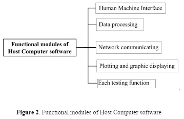
The Host Computer is a high-performance notebook PC, which is connected to the Embedded Controlling Board via Ethernet. The Host Computer sets test parameters and mode by sending commands to the Embedded Controlling Board. By employing Microsoft Visual C++ 6.0 as the software developing platform, taking advantage of the object-oriented programming model, and using the technique of Multiple Document Interface (MDI), the software for Host Computer has been developed to include functional modules such as HMI, graphic displaying, network communicating, data processing, plotting and testing. Functional modules of the software are shown in Figure 2. Own to the sophisticated built-in functions for network applications in Windows, there is no need to develop TCP/IP protocol stack or network drivers anymore. When testing a certain instrument sub, the software can be switched to corresponding functional module and operation interface by making a choice in the menu.
2.2 Design of Embedded Controlling Board
The Embedded Controlling Board realizes functions such as bottom hardware management, test control, and network communication. It uses ARM chip S3C44B0X as the microcontroller, a 10M network interface with isolation in which the Ethernet controller RTL8019AS is integrated; the 16-bit EIOB is designed based on the BANK8 memory space of S3C44B0X. The software system of the board mainly consists of hardware drivers, Real-Time Operating System (RTOS) based on uclinux (Wu et al., 2011) and applications. Hardware drivers are used to controlling hardware devices directly; RTOS realizes multi-task scheduling, inter-process communication management and provides applications with system functions; applications realize various test functions based on the RTOS.
The software design for Embedded Controlling Board mainly refers to the transplantation of embedded operating system and the development of drivers and applications. Hardware drivers are independent of operating system and stored with system files. Upon function calls, they are dynamically loaded into memory in the form of modules. The flow chart of the application program is shown in Figure 3. After the system is powered on, global variables are initialized, at first; then device drivers are called, and bottom layer circuit boards are initialized. The network communication module is used to realize socket connection with Host Computer, where the socket works in the non-block mode and data is sent to Host Computer by a separate thread. The transmitted data frame is defined to consist of a frame head and data segment. Upon arrival of data, the program determines which testing routine the data is sent for by reading and decoding the frame head. Then the data frame is sent to target routine to be processed. Once the test is completed, the program determines whether there is any data to be returned to the Host Computer. If no data is to be uploaded, the program returns and waits for new information. Otherwise, a new thread will be created to send data to the Host Computer and after that, the program returns to wait for new information. The newly created thread will run independently to finish data uploading and then exit.

2.3 Design of functional boards
The functional boards provide circuit interfaces for logging tool or subs. Figure 4 is the hardware structural of functional boards. All the three functional boards are developed based on FPGA and integrated with EIOB for communication with Embedded Controlling Board. The Telemetry Communication Board uses Cyclone EP1C12Q240 by Altera as the controller and is integrated with Controller Area Network (CAN) bus interface. The Bus Interface Board and the Signal Acquisition Board both adopt EP2C20Q240C8 as the microcontroller. The Bus Interface Board provides TMB circuit interface and the simulation signal. The Signal Acquisition Board can perform synchronous data acquisition and processing in up to eight channels at the same time.

All the functional boards software is designed with VHSIC Hardware Description Language (VHDL). From modularization and top-down design strategy, the software is divided into several functional modules that are integrated with the top layer of schematic, making it provided with a simple and intuitional architecture that is easy for maintenance.
The Telemetry Communication Board, which is integrated with two CAN interfaces and can be used to control logging tool or electronic master sub in replace of telemetry sub, realizes functions of responding to commands from Host Computer and storing the uploaded data. Figure 5 gives the structural modules of Telemetry Communication Board software. The main functional modules of the software are bus interface logic module, interruption management unit, and CAN interface module. The bus interface logic module makes an address assignment for the 16-bit EIOB and generates the control bus that performs interface module selection as well as read-write control. Coordinated by the control bus, the internal multiplexer will connect the chosen module to the EIOB. The interruption management unit is used to enable, screen or clear the Interrupt Request (IRQ) from CAN interfaces. The CAN interface modules convert the bus control timing into the address and data bus multiplex timing of SJA1000. Besides, they will respond to interruptions from SJA1000 and issue IRQ to the interruption management unit.

The Bus Interface Board is integrated with TMB interface for highspeed data transmission between internal modules of the downhole instrument, and an acoustic signal generator. The TMB can be used to simulate master or slave node of internal instrument modules by switching the working mode in software. It mainly performs three tasks. First, it receives and analyzes the serial output command from the electronic master sub and then returns the given data. Second, it sends commands to sonic receiving sonde or electronic receiving cabin and returns the acquired data. Third, it provides command strings for testing of sonic transmitting sonde where serial commands are needed. The acoustic signal generator uses the Digital-to-Analog Converter (DAC) AD5541 as waveform generator and produces simulated acoustic signal for testing of electronic receiving cabin (Zhang et al., 2014). The waveform data is stored in FPGA in advance. The analog signal generated by the DAC is provided to corresponding test module after the processing of filtering and impedance matching. Figure 6 gives the software structure of Bus Interface Board, which mainly consists of a bus interface logic module, with functions such as transmitting FIFO, receiving FIFO, transmitting-receiving controller, serial transmitter, serial receiver, waveform storage module, DAC module. The bus interface logic module is mainly used to write in the data to be transmitted, read the received data and control data transmitting and receiving. The transmitting and receiving FIFOs are configured within FPGA, serving as a cache for transmitted or received data storage. The transmitting-receiving controller switches the working mode of the board to make it work in transmitting or receiving mode in turn. The serial transmitter or receiver is constructed of counter and shift register. They perform serial data transmitting and receiving in the charge of the transmitting-receiving controller. The waveform storage module is used to store the simulated waveforms that are prepared in advance. The DAC module governs the digital-to-analog conversion process according to the timing of DAC chip as well as the clock.

The Signal Acquisition Board can to acquire and process analog signals in the eight channels synchronously, and it is used for voltage acquisition of logging tool power supply in this study. After signals are put in, one of them will be selected by the multi-channel time-sharing multiplexer ADG408 to be amplified and filtered and then converted by the Analog to Digital Converter (ADC) AD7677. After the conversion, FPGA stores the data and uploads it if necessary. As shown in Figure 7, the Signal Acquisition Board software consists of bus interface logic module, ADC controlling module, FIFO. The bus interface logic module receives and analyzes the command string from Embedded Controlling Board, breaking it into information pieces such as channel selection, gain factor, sampling control. The channel selection command is used to specify a channel among the eight channels so as to perform signal acquisition in. The gain factor is the number of times signal being amplified before acquisition begins and it ranges from 0 to 90dB with a step of 6dB. The sampling control command is sent to the ADC controlling module to control the sampling process, e.g. initiating or ceasing the process, using setting sampling depth and interval. In particular, the ADC controlling module will assign sampling tasks to AD7677 according to the command received. The FIFO is a 16-bit first-in-first-out register that is configured in the FPGA. It is used for temporary storage of the acquired data, which will then be uploaded to the Embedded Controlling Board by the bus interface logic module via EIOB.

3. Test set-up and results
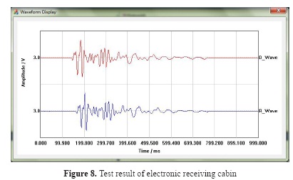
The electronic receiving cabin is a critical as well as a widely used module in sonic logging tool, with its performance significantly affects the accuracy of signal acquisition. In the production of the module, the module test procedure should be too much complex and time-consuming if it is performed only by using basic instruments such as an oscilloscope, multimeter, which obviously is not beneficial to the scale production. Therefore, in this paper, the test-bench is proposed and developed to realize automatic detection of the sonic logging tool. The cabin is power supplied by the test-bench and provided with simulated acoustic signal and TMB interface by the Bus Interface Board. During the test, the Host Computer configures test parameters and issues commands to the Embedded Controlling Board via Ethernet. After receiving the command, the Embedded Controlling Board forwards it to Bus Interface Board via the EIOB. According to the command, the Bus Interface Board will send a simulated acoustic signal to the electronic receiving cabin, read the returned data via TMB interface and finally upload the data to Host Computer by way of Embedded Controlling Board. Figure 8 exhibits the waveform displaying interface of the Host Computer software that shows the test result of electronic receiving cabin. The waveform tagged D_ Wave is the simulated acoustic signal while R_Wave the signal returned by the electronic receiving cabin. From the figure, it can be seen that the two waveforms are almost the same in shape despite the existing of a time lag. Therefore, the electronic receiving cabin module is considered as qualified, and the user may proceed with other tests.
Conclusions
In this paper, a brief introduction is given to the architecture of the test-bench before the system design is discussed in detail. The test-bench system design for sonic logging tool is conducted for the three parts respectively: the Host Computer software, the Embedded Controlling Board, and functional boards. The Host Computer software is written in VC++, which is an object-oriented programming language. The Embedded Controlling Board uses ARM chip as the microcontroller, its software is designed based on a layered architecture with the uclinux operating system serving as the system kernel. The functional boards are designed based on FPGA. The software modules on each board are developed in VHDL language and finally integrated with the top layer of schematic. With the layered architecture and modularized design, the software system is highly reliable and extensible. With the help of designed test-bench, a quick test has been conducted successfully on the particular logging tool module of electronic receiving cabin. To conclude, the test-bench for sonic logging tool has made it easy and time-saving to perform tests on the logging tool or subs, which has a significant meaning in laying foundations for industrial production of the sonic logging tool.
Acknowledgments:
This work is supported by National Natural Science Foundation of China (61102102,11204380,11374371,11134011), National Science and Technology Major Project (2011ZX05020-009), PetroChina Innovation Foundation (2014D-5006-0307), China National Petroleum Corporation (2014B-4011,2014D-4105,2014A-3912) and Science Foundation of China University of Petroleum, Beijing (2462015YQ0516).
References
Ju, X.D., Cheng, X.Y., Lu, J.Q., Xu, W., Men, B.Y. and Wu, W.H. (2009). Design of Test-bench System for Logging Tools Based on Embedded Structures. Well logging technology, 33(3), 270-274.
Lu, B.P., Qin, L. and Zhang, Q.J. (2005). Multiple function test tables for well logging instruments. Petroleum Instruments, 19(6), 17-19.
Lu, J.Q., Ju, X.D., Men, B.Y. (2012). Design of test platform for receiver mandrel of multi-pole array acoustic logging tool. In: Fuzzy Systems and Knowledge Discovery (FSKD), 2012 9th International Conference on IEEE, 2660-2663.
Lu, J.Q., Ju, X.D., Men, B.Y., and Wu, W.H. (2010). Study on Test Method for Transmitter Mandrel of Acoustic Logging Tool Based on ARM. Well logging technology, 34(4), 389-392.
Men, B.Y., Ju, X.D., Qiao, W.X., Cheng, X.Y. and Lu, J.Q. (2011). Design of Test-bench System for the Multi-frequency Array Induction Imaging Logging Tool Based on Embedded Structures. Science technology and engineering, 11(11), 2450-2454.
Wu, W.H., Ju, X.D., Cheng, X.Y., Lu, J.Q. and Deng, L. (2011). Design of front-end computer software for logging tool test-bench based on liClinux. Journal of China University of Petroleum, 35(3), 63-66.
Yan, Z.G., Zhang, J.T., Qin, L. and Zhang, Q.J. (2008). Development of the self-test unit for EILog complete logging equipment. Petroleum Instruments, 22(1), 12-14.
Yang, X.F., Ju, X.D. and Wu, W.H. (2012). Design of the communication software for logging tool test-bench based on B/S model. Journal of China University of Petroleum, 36(3), 88-92.
Zhang, K., Ju, X.D., Lu, J.Q. and Men, B.Y. (2014). Design of acoustic logging signal source of imitation based on field programmable gate array. Journal of Geophysics and Engineering, v.11(4), 45008-45013. DOI: https://doi.org/10.1088/1742-2132/11/4/045008.
How to Cite
APA
ACM
ACS
ABNT
Chicago
Harvard
IEEE
MLA
Turabian
Vancouver
Download Citation
CrossRef Cited-by
1. Y. C. Yao, B. H. Tan, K. Zhang. (2019). A general experimental system for the development of acoustic logging tools. Review of Scientific Instruments, 90(4) https://doi.org/10.1063/1.5082342.
Dimensions
PlumX
Article abstract page views
Downloads
License
Earth Sciences Research Journal holds a Creative Commons Attribution license.
You are free to:
Share — copy and redistribute the material in any medium or format
Adapt — remix, transform, and build upon the material for any purpose, even commercially.
The licensor cannot revoke these freedoms as long as you follow the license terms.
The Earth Sciences Research Journal is the copyright holder for these license attributes.