CONSTRUCTION OF LOW COST SPIN AND DIP COATERS FOR THIN FILM DEPOSITION USING OPEN SOURCE TECHNOLOGY
CONSTRUCCIÓN DE SPIN Y COATER DE BAJO COSTO PARA DEPOSICIÓN DE PELÍCULAS DELGADAS UTILIZANDO TECNOLOGÍA DE PLATAFORMA ABIERTA
Keywords:
Spin coater, Dip coater, Thin films, Surface deposition, Open source, Low cost (en)Spin coater, Dip coater, Películas delgadas, Deposición, Plataforma abierta, Bajo costo. (es)
A novel low cost method was developed for the construction of a spin
coater and a dip coater device incorporating inexpensive mechanical
components and open-source software. Both devices are utilized for
depositing thin films, and can be built with interdisciplinary
knowledge of physics, mechanics, and electronics at the undergraduate level. The spin coater permits a wide speed range (from 500 to 10,000 rpm), and the velocity range of the dip coater stretches (from 0.6 cm/h to 30 cm/min). The operational parameters of these instruments compare favorably with commercial models.
Se ha desarrollado un nuevo método para la construcción de
dispositivos de spin coater y dip coater incorporando componentes
mecánicos económicos y con software de plataforma abierto. Ambos
dispositivos se utilizan para la deposición de películas delgadas, y
se pueden construir con el conocimiento interdisciplinario de la
física, la mecánica y la electrónica a nivel de pregrado. El spin
coater permite un amplio rango de velocidad (de 500 a 10.000 rpm) y el rango de velocidad del dip coater es (de 0.6 cm/h a 30 cm/min).
Estos parámetros operacionales se comparan favorablemente con los
modelos comerciales.
CONSTRUCTION OF LOW COST SPIN AND DIP COATERS FOR THIN FILM DEPOSITION USING OPEN SOURCE TECHNOLOGY
CONSTRUCCIÓN DE SPIN Y DIP COATER DE BAJO COSTO PARA DEPOSICIÓN DE PELÍCULAS DELGADAS UTILIZANDO TECNOLOGÍA DE PLATAFORMA ABIERTA
David Loza M.1, Victor H. Guerrero2, Reza Dabirian1,2
1Departamento de Ciencias de la Energía y Mecánica, Universidad de las Fuerzas Armadas–ESPE, Sangolquí, Ecuador
2Laboratorio de Nuevos Materiales, Departamento de Materiales, Escuela Politécnica Nacional, Quito, Ecuador.
(Recibido: Noviembre/2014. Aceptado: Diciembre/2014)
Contacto: Reza Dabirian dabirian@gmail.com
Abstract
A novel low cost method was developed for the construction of a spin coater and a dip coater device incorporating inexpensive mechanical components and open–source software. Both devices are utilized for depositing thin films, and can be built with interdisciplinary knowledge of physics, mechanics, and electronics at the undergraduate level. The spin coater permits a wide speed range (from 500 to 10,000 rpm), and the velocity range of the dip coater stretches (from 0.6 cm/h to 30 cm/min). The operational parameters of these instruments compare favorably with commercial models.
Keywords: Spin coater, Dip coater, Thin films, Surface deposition, Open source, Low cost
Resumen
Se ha desarrollado un nuevo método para la construcción de dispositivos de spin coater y dip coater incorporando componentes mecánicos económicos y con software de plataforma abierto. Ambos dispositivos se utilizan para la deposición de películas delgadas, y se pueden construir con el conocimiento interdisciplinario de la física, la mecánica y la electrónica a nivel de pregrado. El spin coater permite un amplio rango de velocidad (de 500 a 10.000 rpm) y el rango de velocidad del dip coater es (de 0.6 cm/h a 30 cm/min). Estos parámetros operacionales se comparan favorablemente con los modelos comerciales.
Palabras clave: Spin coater, Dip coater, Películas delgadas, Deposición, Plataforma abierta, Bajo costo.
Introduction
Thin films of both organic and inorganic materials have found a growing number of scientific and engineering applications over the past decades. They perform the same function when it comes to surface processes compared to the corresponding bulk material, yet are much more economically viable Thus, knowledge and determination of the nature, functions and new properties of thin films can be used for the development of new technologies for future applications in high–tech industries. By employing any of the great number of substrates that are accessible, an enormous variety of thin films, each with its own specific characteristics is available for preparation. However, care should be taken to be able to deposit the thin films in such a way as to achieve the desired characteristics regarding, film thickness, homogeneity andreproducibility of the thin films. Over the years many methods have been developed for thin film deposition, they generally can be classified as either chemical or physical deposition. Two of the most common methods to achieve thin films by deposition from a solvent are spin coating and dip coating. In spin coating a smallamount of solution is deposited onto the center of a substrate which is subsequently spun at high speeds. Factors that affect
the coating process include speed of spinning, acceleration, spin time, exhaust, the viscosity and concentration of the solution.[1] Another important factor in spin coating is repeatability, as subtle variations in the parameters that define a spin–coating process can result in drastic variations in the coated film. Dip coaters are designed to deposit layers of materials in a controlled and repeatable way. It works as a substrate is submerged in a solution and then in a controlled and constant fashion retracted from the solution.[2] Dip coaters provide homogeneous and smooth films.
The thickness and internal layer structure of such films can be adjusted by altering the concentration of the solution, retracting speed and/or by having multiple dipping cycles. Therefore, given their ease of use, spin and dip coaters are amongst the most ubiquitously used instruments for the fabrication of thin films in many laboratories. However many commercial spin and dip coaters are prohibitively expensive and may have features are not necessarily needed for fabrication of thin films. To this end, there have been several reports of the construction of either low cost spin coaters or dip coaters in literature.[3—5]
Often the costs of the commercial models are inflated because of extra features that at times are unnecessary and sometimes even disadvantageous. Two examples of this are the vacuum suction systems and drain bowls that are features of some commercial spin coaters. The former effectively limits the minimum sample size and the latter leads to an unhealthy accumulation of excess coating solution, which is better and easier to dispose of immediately.
The current work presents a novel low cost method for the design and construction of prototypes of a both spin coater and dip coater, with each device incorporating inexpensive mechanical components and open-source software [6, 7] at a fraction of the commercial cost and with operating parameters that compare very favorably to such models. To the best of our knowledge, this is the first report of a spin coater and dip coater being constructed together using the same Arduino based, open source, control unit. A further advantage of our models is that the control units which are programmed using Arduino microprocessors are interchangeable, needing only to be reprogrammed in order to be used in either one of the two instruments.
Experimental
Design of the spin coater
An important objective was the design and construction of a system based on an open source platform that meets the predetermined specifications regarding velocity range, sample size capacity and programming ability of the instruments. Amongst the prerequisite features of the spin coater was the ability to allow the deposition of thin layers upon substrates ranging up to 3X3 cm2 in size, incorporation of an electronic circuit designed to control the speed and spin range from 300 rpm to 10,000 rpm and that the velocity swift should be instantaneous, i.e. without a gradient. The design of the device incorporated three main parts; the mechanical system, the electronic control system and the user interface.
Design of the dip coater
Amongst the prerequisite features that were decided upon for the dip coater was the ability to handle samples ranging from 1X1 cm2 up to 5X10 cm2 in size. Furthermore, a velocity range from at least 1.0 cm/h up to 10 cm/min was desired. These parameters were successfully integrated into the final model by using two separate DC motors of different velocities connected to a 24V power supply and two sets of rack and pinions, effectively affording four distinct ranges of velocity to our system. The total range of velocity that can be accessed by the system stretches from 0.6 cm/h to 30 cm/min, which is larger than that of many commercial models. Furthermore, the open-source Arduino microcontroller allows manual control of the immersion and retraction speed of the device with push button switches.
Construction of the spin coater
The three main components in the construction of the spin coater were; the mechanical system, the electronic control system and the user interface. The mechanical part consists of the support structure of the system, the 12W DC motor with its power supplyand the rotating disk upon which the sample is deposited. Therotational movement of the system is provided by a Brushless DC electric motor. The speed of the motor is controlled by varying the voltage according to the pulse width modulation technique (PWM), using the analogWrite program of the Arduino microcontroller [8] on a scale of 0—255, with the analogWrite (255) resulting in the maximum spin velocity of 15000 rpm. However, for practical applications it was conditioned for values between 300 and 10000 rpm. The connection between the microcontroller and the Arduino DC motor is achieved by a L298N shield, themain attributes of which the capacity to handle up to 25 W and 2 A of current. The motor shaft is connected to a rotating diskupon which the substrates are placed using double-sided tape.The purpose of the control system is to drive the device. Its maincomponent is an Arduino 1 free microcontroller (www.arduino.cc). It is able to receive data from the user interface, process the data and to send it to the DC motor. The microcontroller drives the device by using an open-loop control algorithm in order to regulate the speeding spin. The control system is responsible for maintaining constant speeds and spin duration according to user selection. Speed variations may be between 300 and 10000 rpm for up to 3 minutes.
Construction of the dip coater
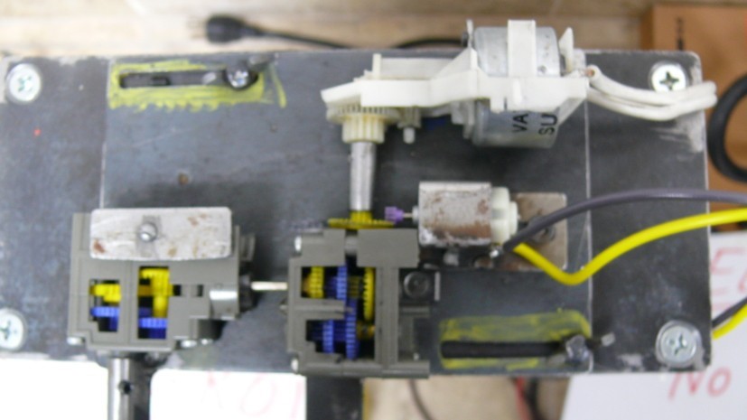
Similarly to the spin coater, the dip coater device consists of three main parts; the mechanical system, the electronic control system and the user interface. The mechanical part consists of the support structure of the system, two DC motors, two power sources of 5 and 24V, gearboxes and a rack and pinion system for linear movement of the sample. The rotary motion of the pinion is achieved through multiple pairs of gears located on three gearboxes. Thus the speed is controlled both electronically and mechanically. The electronic engine speed is controlled by varying the voltage according to the PWM technique, such that analogWrite (255) would result in the maximum pinion rotation of 3000 rpm. A pinion–rack system connected to the gearboxes enables the conversion of rotary motion to linear motion. To achieve as wide a range of velocities as possible the system was fitted with two interchangeable wheels. The largerwheel has a radius eight time the smaller wheel, meaning that the larger wheels will result in eight times the velocity of the smaller wheel for any given voltage (Figure 1). As the system encompasses two independent DC motors, this effectively results in four distinct velocity ranges (Figure 2). Furthermore, as both motors make use of the same axis, the one that is not in use must be manually disengaged before starting a new test to avoid damage to the mechanical system. As in the case of the spin coater, the connection between the microcontroller and the Arduino DC motor is achieved by a L298N shield to control the two motors, and both the speed and direction of the rotation. Another consideration is the settings of the gearboxes, motors, and rack and pinion mechanisms, which should be secured to avoid vibrations which otherwise could be transmitted to the sample and cause defects such as jumps and holdups during the experiments. Finally, it has to be mentioned that the mechanical system must be very robust, and assembled on a totally at surface. To this end it the base of the system was fitted with a protective layer of thick rubber.

Figure 1.Side by side view of the two wheels used for the dip coater. The larger wheel has a radius eight time the smaller wheel, meaning that the larger wheels will result in eight times the velocity of the smaller wheel for any given voltage.

Figure 2. Top view of mechanical structure of the dip coater with the two independent DC motors visible.
Validation of the instruments
As mentioned earlier the repeatability and reliability of the spinning and dipping speed are crucial factors. To study these operating characteristics of the system, a series of tests was conducted. In order to correlate the actual rotational velocity values vs. PWM for each instrument, several tests undertaken with PWM values ranging between 0 and 255. In the case of the spin coater an Arduino program written specifically for this purpose was used and a digital tachometer employed to measure the output in rpm. Similarly, in the case of the dip coater, the PWM values were correlated to the dipping and withdrawing speeds of the dip coater. The dipping and withdrawing speeds of the dip coater were measured using a simple stop watch and a ruler attached to a vertical stand next to the path of the sample. This enabled us to correlate and validate the spin and dipping speeds against a set PWM value. Thus, to apply any speed within the operating range of the instruments all that is required is to know the corresponding PWM value and to inset that value to the Arduino based program using the push button switches on the user interface.
Results
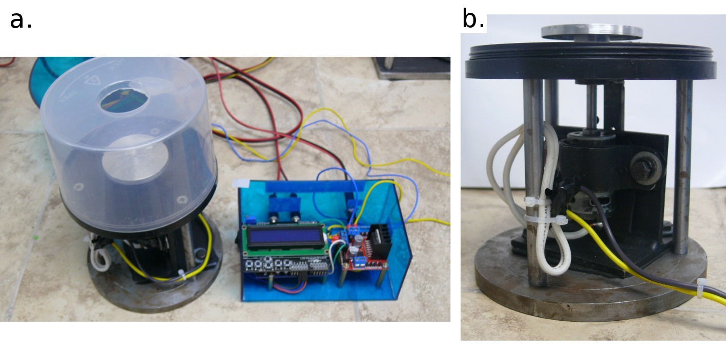
The spin coater is constructed with a single DC motor acquired from a printer and an open-source Arduino microcontroller designed to control the spinning speed and spinning time and it is powered with a 12V power supply. The substrate is mounted using a double–side tape. It offers manual control with push button switches, a wide speed range (from 500 to 10,000 rpm), spin speed stability and compact size. The spin velocity is controlled by the Arduino microcontroller. The system allows depositing thin films of any dissolved materials at rotational speeds between 300 and 5000 rpm with an error of ±1% rpm. The magnitude of variation of the spin velocity is constant and attributed to the fluctuations of the mains voltage which feeds the Arduino. It is comparable to many commercial models and does not impede the reproducibility of the obtained thin films. Figures 3a and 3b show the finished spin coater.
Typically for spin coating the user selects two velocities for each deposition. A low velocity of 500 rpm is initially chosen for about three seconds. The purpose of this is to dispense the fluid on top of the substrate and to spread the fluid over the substrate. This is followed by an instantaneous switch in velocity up to anywhere from 1000 to 10000 rpm. The purpose of this high speed spin step is to thin the fluid, to eliminate excess solvents from the resulting film by drying it.
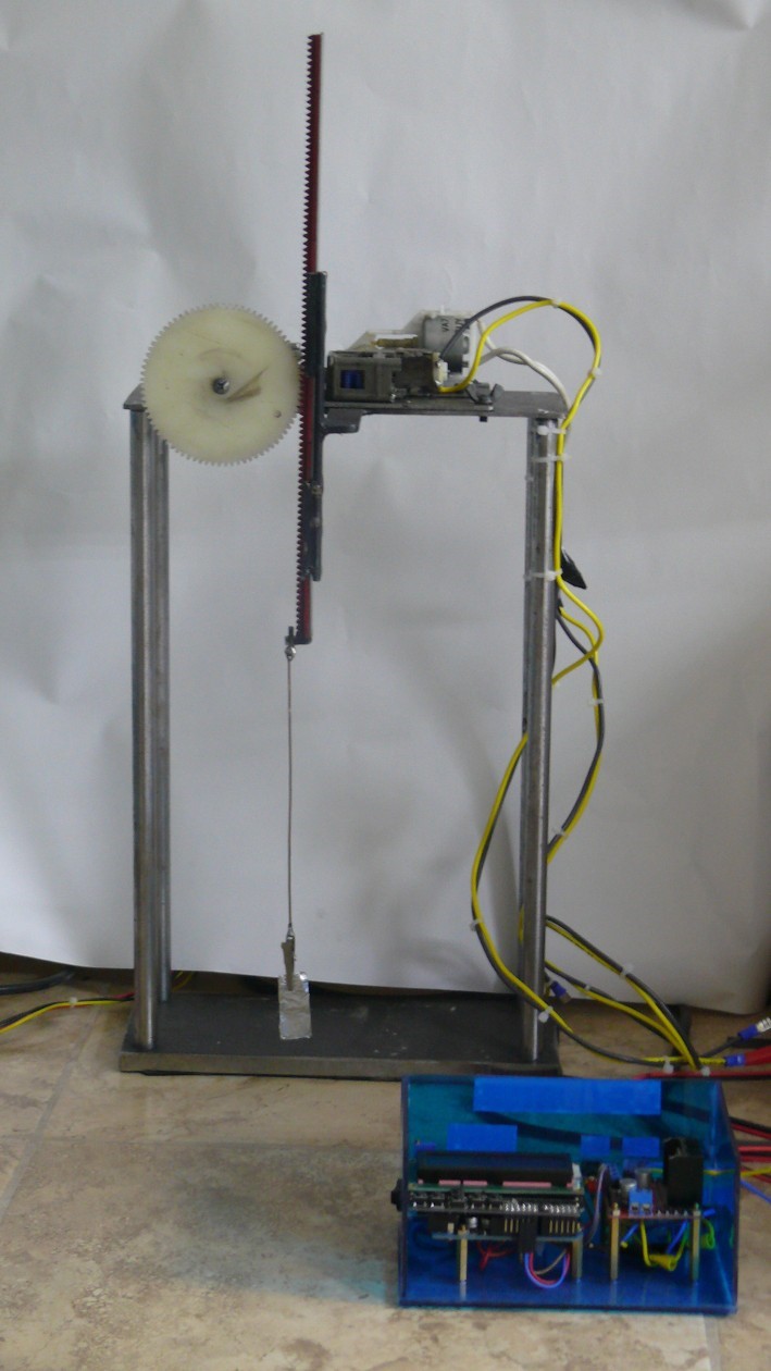
The dip coater system allows depositing thin films at line speeds between 0.6 cm/hr and 30 cm/min with an error of ±2% due to voltage variation in the network. The substrate is attached to the alligator clip at the end of the wire. Figure 4 shows the finished dip coater. The electronic control system and user interface are basically identical to that of the spin coater, with the added option to change the direction of the rotation. This is due to the fact that often different speeds are required for approaching (lowering) and retraction (lifting) of the sample. Before each experiment the user selects the approaching and retracting speeds independently

Figure 3. Top view of the spin coater with Arduino based microcontroller (left) and side view (right). The substrate is mounted using a double–side tape.
with push button switches. The amount of time that the system is retracting can also be set. However the system is designed such that the approach takes place by keeping the approach button pressed in. This facilitates the entry of the sample probe into the solution, as it offer a higher degree of control to terminate the approach at exactly the desired point, which is usually just beneath the solution level, when the sample is totally immersed into the solution. It is also a practical measure as approaching speeds are generally much higher than retraction speeds. The retraction speed is considered considerably more critical as it must be very uniform and constant. To this end the user can select the time it could take for the sample to withdraw from the solution. The available options range from minutes to hours, even for samples as small 1×1 cm2.
For both instruments a KeyPad Shield LCD was employed as the user interface, which provides a graphical, convenient, simple and easy to use controlling device. The user interface is programmed in Arduino and allows a selection of speed and duration of the spinning with push button switches.

Figure 4. Front view of the dip coater with Arduino based microcontroller to the right. The substrate is attached to the alligator clip.
Discussion
A significant advantage of the constructed models is the ease of use of the two instruments. This has to do with the simple design of the Arduino based electronic control system and user interface, which is interchangeable and can be used for either of the two instruments. The only requirement for switching the control unit from one instrument to the next is the reprogramming of the control program, as some functions need to be slightly altered. The control unit can potentially also be used for other instruments.
Both instruments were entirely assembled using parts exclusively available in the local market (Ecuadorian) for purchase, with no need for any expensive imported parts. The total expense for the components of the spin coater was less than $200, which is to be compared with commercial models that range from $800 to $5000. The cost of the components of dip coater was $ again the price of the cheapest commercial models starts at $1200 and can easily reach several times that amount. This makes our design very viable, as it should be straightforward to replicate, and made assessable to industrial and academic research groups. Thus, allowing the possibility to access to an even more wide range of thin films on substrates.
Spin coating is widely used in microfabrication where it can be used to create thin films with thicknesses below 10 nm. In spin coating the there are various parameters that need to be taken into consideration. Among them are the speed of spinning, the viscosity and concentration of the solution, acceleration, spin time and exhaust. However, the process parameters vary greatly for different materials and substrates so there are no fixed rules for spin coat processing, only general guidelines. Of critical importance is that the process is reproducible. In order words, that the processing parameters can be adequately controlled. During the validation process, our spin coater has shown to meet the requirement for reproducibility as both the spinning speed and acceleration is controlled by the Arduino program and is thus reliable.
In the case of dip coating, a substrate is immersed and subsequently withdrawn from a reservoir of liquid for the purpose of depositing a layer of material. It is essential that the retraction speed is stable in order to avoid inhomogeneities and/or steps in the thin films. Similarly to the spin coater, the retraction speed of our dip coater is controlled by the Arduino microprocessor. As the retraction speed is very slow (typically less than 1 cm/min) the retraction speed is very slow and the voltage needed to operate the two motors is minimal, fluctuations of the retraction speed is not an issue with our system and our system is able to deliver uniform, high quality films even on bulky, complex shapes.
Dip coating is used for the fabrication of thin films by self–assembly of controlled thickness, determined mainly by the deposition speed and solution viscosity There are, just as in spin coating, a variety of factors to account for when determining the final state of the thin film when dip coating a given substrate. Among the factors, that affect the process are the submersion time, withdrawal speed, number of dipping cycles, solution composition, concentration and temperature and environmental humidity.[9] An in depth discussion of each of these factors and their influence on the final morphology of the film is beyond the scope of this article. However, just as in spin coating the reproducibility of the system i.e. reliability of the withdrawing speed is of utmost importance. For the dip coater, this speed parameter is controlled by the Arduino program and the successful validation of the instrument ensures reliable and constant dipping and withdrawing speeds.
Conclusions
We have reported the construction of both a spin coater and dip coater being constructed together using the same Arduino based, open source, control unit. Furthermore, we have demonstrated the possibility to construct low cost, high quality scientific instruments by employing readily available mechanical parts and open source software. The mechanical properties of our spin coater (speed range from 500 to 10,000 rpm) and dip coater (withdrawing speed range: from 0.6 cm/h to 30 cm/min) compare favorably with commercial models. The main advantages of these instruments are their low cost, ease of use and robust and stable design. They represent a new generation of low cost instruments that will enable research groups the possibility to conduct research that was previously out of reach due to the prohibitive costs that until very recently were associated with them.
Acknowledgements
We wish to thank Dr Victor H. Guerrero for fruitful discussions and Hernan Lara and Andrea Orbe for their efforts during the assembly of the instruments. This work was supported by the Prometeo Project of the Ministry of Higher Education, Science, Technology and Innovation of the Republic of Ecuador (SENESCYT) for their sponsorship in this work.
References
[1] D. B. Hall, P. Underhill, and J. M. Torkelson, Polym. Eng. Sci.38, 2039 (1998).
[2] J. Puetz and M. Aegerter, in Sol–Gel Technologies for Glass Producers and Users, edited by M. Aegerter and M. Mennig (Springer US, 2004) pp. 37–48.
[3] M. Fardousi, M. F. Hossain, M. S. Islam, and S. R. Ruslan, J. Mod. Sci. Technol. 1, 126 (2014).
[4] R. Gómez–Aguilar and J. Ortiz–López, Lat. Am. J. Phys. Educ. 5, 368 (2011).
[5] S. El–Yamny and M. Abdel–Rafea, J. Mod. Phys. 3, 1060 (2012).
[6] D. K. Fisher and P. J. Gould, Mod. Instrum. 1, 8 (2012).
[7] J. M. Pearce, Science 337, 1303 (2012).
[8] Arduino, http://arduino.cc/en/reference/analogwrite/, (2014).
[9] Biolin–Scientific, http://www.biolinscientific.com/technology/dip-coating/, (2014).
How to Cite
APA
ACM
ACS
ABNT
Chicago
Harvard
IEEE
MLA
Turabian
Vancouver
Download Citation
Article abstract page views
Downloads
License
Those authors who have publications with this journal, accept the following terms:
a. The authors will retain their copyright and will guarantee the publication of the first publication of their work, which will be subject to the Attribution-SinDerivar 4.0 International Creative Commons Attribution License that permits redistribution, commercial or non-commercial, As long as the Work circulates intact and unchanged, where it indicates its author and its first publication in this magazine.
b. Authors are encouraged to disseminate their work through the Internet (eg in institutional telematic files or on their website) before and during the sending process, which can produce interesting exchanges and increase appointments of the published work.


