
Published
Designing and simulating a nitinol-based micro ejector
Diseño y simulación de un micro eyector basado en nitinol
DOI:
https://doi.org/10.15446/ing.investig.v32n1.28519Keywords:
shape memory alloy (SMA), nitinol, nitinol membrane (en)AMF, Aleación con Memoria de Forma, Nitinol, Eyector, Membranas de Nitinol (es)
This paper describes pico-droplet ejector design and simulation. The actuation system was based on two interconnected nitinol membranes' shape memory effect. Ejected volume was 12pL and it operated at 30°C to 64°C. Ejecting excitation voltage was 12V and the ejecting energy required by actuator operation was 26µJ per drop. These pico-liter ejectors could have applications in making, lubricating and cooling integrated circuits.
Este artículo describe el diseño y simulación de un eyector de pico-volúmenes cuyo sistema de actuación está basado en la memoria de forma de dos membranas de Nitinol. El volumen de las gotas eyectadas es de 12pL. El micro eyector opera a temperaturas entre 30°C y 64°C, a un voltaje de 12 V y una energía de eyección de 26µJ por gota. Este tipo de eyectores puede tener aplicaciones en la fabricación con tintas conductoras, lubricación y el enfriamiento de dispositivos electrónicos.
Designing and simulating a nitinol-based micro ejector
Diseño y simulación de un micro eyector basado en nitinol
Yesid Mora Sierra1, Alba Ávila Bernal2,
1 Electronic Engineer, Universidad Pontificia Bolivariana, Colombia. MSc in Electronic Engineering, Universidad de los Andes, Colombia. juanfmartinezp@gmail.com.
2 Electrical Engineering and physicist, Universidad de los Andes, Colombia. PhD, Cambridge University, England. Associate Professor Electrical and Electronic Department, Universidad de los Andes. Member of the Microelectronics Center at Universidad de los Andes (CMUA). Corresponding author email: a-avila@uniandes.edu.co.
Received: January 25th 2011; Accepted: February 8th 2012
RESUMEN
Este artículo describe el diseño y simulación de un eyector de pico-volúmenes cuyo sistema de actuación está basado en la memoria de forma de dos membranas de Nitinol. El volumen de las gotas eyectadas es de 12pL. El micro eyector opera a temperaturas entre 30°C y 64°C, a un voltaje de 12 V y una energía de eyección de 26µJ por gota. Este tipo de eyectores puede tener aplicaciones en la fabricación con tintas conductoras, lubricación y el enfriamiento de dispositivos electrónicos.
Palabras clave: AMF, Aleación con Memoria de Forma, Nitinol, Eyector, Membranas de Nitinol.
ABSTRACT
This paper describes pico-droplet ejector design and simulation. The actuation system was based on two interconnected nitinol membranes' shape memory effect. Ejected volume was 12pL and it operated at 30°C to 64°C. Ejecting excitation voltage was 12V and the ejecting energy required by actuator operation was 26µJ per drop. These pico-liter ejectors could have applications in making, lubricating and cooling integrated circuits.
Keywords: shape memory alloy (SMA), nitinol, nitinol membrane.
Introduction
Inkjet printing is the most commonly used application for producing microlitre to picolitre volumes (Smith, 2009, p. 91-99) using the drop-on-demand (DoD) principle. The droplets are produced and injected into an internal print head forming part of the cartridge used in inkjet printing. The print head contains nozzles, the liquid to be ejected (ink) and the heaters. The heaters' function is to bring the ink to its boiling temperature (T>300°C), thereby creating a bubble that is then pushed out of the nozzle. Such print heads are some of the devices providing the greatest benefit in the market for electromechanical systems (MEMS) (Aarkstore, p. 45) and are a major component in the field of microfluidics (Xu, 2009, p. 1-10).
This technique can be useful for ejecting other types of fluid; however, it has only been applied to liquids which can be brought to their boiling point without being affected or changed, as is done with ink (Gad-el-Hak, 2005, p. 30.1-30.7). This research was aimed at exploring alternative pico-droplet generation to those currently used in inkjet injection print heads. ANSYS v10.0 (AN-SYS) was used for such multi-physics design and simulation regard-ing a picolitre droplet ejector whose performance was based on the implicit property of shape memory function concerning the temperature of materials known as shape memory alloys (SMA). SMAs are metal alloys which remember their original shape and have two phases: martensite and austenite. The material is easily deformable in the martensite phase whilst the material has the greatest opposition to deformation during the austenite phase (being the phase during which a material returns to its original shape by means of a rise in temperature). Simulating these two phases in SMAs imposed challenges in integrating structural changes due to thermal changes in multi-physics tools because there are no mechanical-thermal coupled models for SMAs.
Micro-ejector drop ejection was controlled by the movement of two SMA membranes defining three operating states: supply, rest and ejection; this involved 30°C to 64°C membrane phase transitions, this being a lower temperature range than that used in conventional DoD thermal injection (>300ºC, Hewlett Packard and Canon). Achieving these temperatures in research is not difficult if heaters are used (e.g. heating resistors) or if the heat generated by integrated circuits or microprocessors is reused (Hamann, 2007, p. 56-65). Stress curves compared to deformation at different temperatures were included for SMA circular membrane simulation allowing the necessary membrane deflections needed to displace 12pL to be determined. The temperature in each membrane was independently controlled by two electric heaters whose geometries and dimensions were optimised to create uniform temperature changes. The effects of heat transfer between the different inter-faces were analyzed. The membranes, heaters, reservoir and fluids were all taken into account in membrane deformation and consequently during droplet generation.
Small volume droplet control greatly affects micro-scale device manufacture, manipulation and operation. Resolution lithography and deposition can benefit from using of small volumes of sensitive films, conductive polymers and porous agglomerates (already reported in manufacturing devices using jet printing techniques) (Calvert, 2001, p. 3299-3305). This could also lead to benefits in reducing moving micro parts' wear by generating lubricant pico-volumes (Gadel-Hak, 2005, p.11.1-11.9) and benefits in the complex assembly of hybrid devices in which small amounts of adhesive (resin) and welds are used (Suhir, 2007, p. 487-525). Other applications include the ejection of pico-drops of refrigerant and the application thereof as a method of calibrating atomic force microscope elastic constants using mass addition methods (Golovko, 2007, p. 1-6, Avila, 2007, p. 25-32).
Pico-volume ejector design
Figures 1a and 1b describe the pico-volume ejector geometry in detail. This consisted of an ejection system controlled by two circular nitinol membranes (nickel-titanium SMA), a reservoir, an ejector nozzle and a check valve. The function of this valve was to prevent reverse flows from being generated in the reservoir fluid inlet.

The ejector dimensions were determined from simulations which took the following into account: membrane size and free deflection, one membrane's location in relation to the other, the appropriate volume of fluid to be ejected and ejector nozzle size (see Figures 1c and 1d). M1 (the membrane in contact with air) and M2 (the membrane in contact with fluid) were the pico-volume ejector's membranes and were made of a specific 1wt % Ni- Ti 44 (nitinol) alloy (Serneels, 1990, p. 6-23). This alloy returned to its original shape when heated to a transformation temperature greater than or equal to 60°C (Donohue, 2008).
Figure 1d shows M1 and M2 configuration and the respective heating systems controlling transitions between phases. M1 and M2 movement was not independent but governed by a solid having thermal-electrical insulating properties connecting the membranes. Joining both membranes allowed repetitive droplet ejection movements without resorting to devices producing external pressure on the membranes. It should be noted that each membrane shown in the Figure was not in contact with the heating resistor, but separated by an electrical insulator resisting load transfer but allowing for the transfer of thermal energy. The heaters' function was to produce temperature gradients which could bring M1 and M2 from the material's martensite phase (easily deformed) to the austenite phase (difficult to deform) (Paiva, 2003, p.1-30). Manipulating M1 and M2 phases led to defining the ejector's three operating states.
The supply (Figure 1a), ejection (Figure 1b) and standby (Figure 1c) operating states were directly related to M1 and M2 deformation. In the supply position, M1 and M2 allowed the entry of fluid into the reservoir through the check valve, heating M1 and keeping M2 at room temperature (TA ≤ 30°C). This temperature configuration brought M1 to the austenite phase to displace M2 which was in the martensite phase. Ejection allowed the fluid from the reservoir to be released, temperature reversed and therefore M1 and M2 phases (i.e. M2 heated up and M1 remained at room temperature). Standby was an intermediate state for switching between states of supply and ejection in which M1 and M2 were at ambient temperature (see Figure 1c). Table 1 summarises the membranes' phase transition temperatures for each state.
Because of the membranes' configuration (anchored at the contour and connected at its midpoint; see Figures 1c and 1d, respectively), their movements were not independent and maximum displacement occurred in the centre. This shift was crucial for ejector supply and ejection states where both membranes' phases were opposite (see Table 1). The simulated ratio of maximum displacement between membrane martensite phase (DM) and austenite phase (DA) was:

This ratio confirmed a difference between maximum 4.58µm membrane displacement (DM-DA) to ensure that it could produce comparable volumes handled by jet printers (12 pL; see Figure 2a). The maximum simulated stress experienced by M1 and M2 for these deflections did not exceed 61MPa. This stress value was well below nitinol breaking point (1.5GPa) (Schaffer, 2003, p. 109-118), thereby reducing potential membrane fracture/failure.

Figure 2b shows stress compared to strain curve for simulated nitinol membrane austenite phase. This demonstrated that a membrane has no deformations remaining when applying load cycles at this stage. It can thus be seen from the curve that one always reached the point of zero strain by discharging the material. Each membrane is shown when it was in this phase through a circle showing the working region in which each membrane was at this stage (σ ≤ 61MPa). It should be noted that this curve could only be displayed in ANSYS by summing the material's elastic and plastic stress components since these took into account the deformation of the crystal lattice that related all the necessary atomic movements for the transformations between the austenite and martensite phases. If all the components were not taken into account, the results of stress and strain would only have corresponded to the material's elastic component, thus obscuring typical SMA hysteresis.

Heating resistor design
Figure 3a shows the geometry chosen for the heating resistors. The selection criterion was based on least opposition to membrane deflections and most uniform temperature distribution. Figure 3b shows reduced heating resistor and electrical insulation cross-sectional area around the membranes' contour which is necessary for reducing heat transfer effect to the base supporting M1 and M2 (base PMMA in Figure 1b) and thus ensuring a more uniform temperature for each membrane. Having a uniform temperature ensured that the entire membrane area regained its original shape when it was in the austenite phase, as defined for supply and ejection states (concerning M1 and M2, respectively). Transformation temperature must be greater than or equal to 60°C at this stage (see Table 1). If any part of the membrane had a lower temperature, the membrane would not fully recover its original shape and therefore the ejector would not generate uniform volume droplets. Figure 3c shows the results of reducing the heater's cross-sectional area near the contour concerning M1 temperature distribution; in this case, temperature variations less than 5°C were displayed between the centre and the contour for 75% reduction
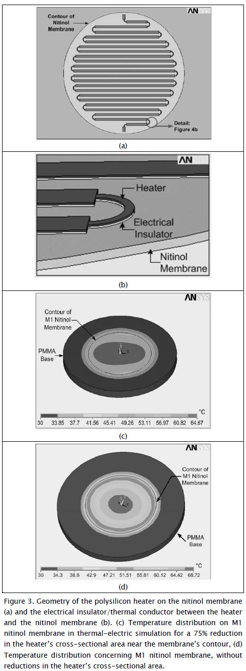
of cross-section area compared to original area (0.2µm2). Greater than 15°C temperature differences occurred when excluding such reduced area in the heater (see Figure 3d).
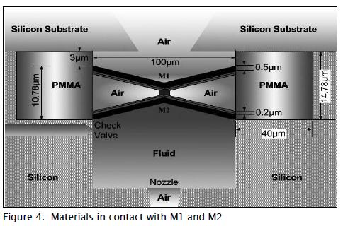
Response times
M1 and M2 were not thermally insulated in the pico-volume ejector (Figure 4); their temperature could have been dissipated as they were in contact; M1 was in contact with the air and PMMA walls, M2 was in contact with the air, the fluid (density, viscosity, surface tension and thermal conductivity of water were taken as fluid properties) and PMMA walls. The aforementioned contact conditions affected response times in each membrane's transition phase. The simulations showed that the ratio between membrane heating times was M1/M2=0.91 and the ratio between cooling time was M1/M2=0.93. When M2 was in contact with both air and fluid, it took longer to reach phase transition temperatures.
Applying voltage pulses to the heating resistors determined minimum pulse width able to produce a change from martensite phase to austenite phase and vice versa in the slower membrane (M2) (Figure 5a). The centre of M2 took 11.9ms (heating time) to reach 64.6°C, ensuring 60°C in its contour; conversely, M2 took 22.3ms (cooling time) to reach ambient temperature throughout its volume.
Figure 5(b) shows a diagram of the timing that the applied voltage pulses should have had for the two resistors to eject droplets continuously (state cycles: supply, standby, ejection and standby and supply) where T symbolises the time taken for a droplet to be ejected. The device's maximum operating frequency was thus around 15Hz.
Results
Droplet ejection was validated from displacement profiles Uy (Equation 1) and speed at each point on membrane Vy (Equation 2) determined in the simulations for M2:

t represents the respective split times for each pico-volume ejector state, X the position of any point on the membrane, L membrane radius and i identifies the sequence of states: supply (i=0), standby (i=1), ejection (i=2), standby (i=3) and supply (i=4).
Figure 6 shows drop ejection results for the sequence of states i=0,1, 2. A 12pL volume drop was estimated from these results for 12V applied voltage and 26µJ per drop energy.


Conclusions
A 12pL pico-volume ejector was designed and modelled. Its ejection principle was based on the shape memory of a system having two nitinol membranes joined at their centres and anchored at their contours. The actuation method for the ejector did not require external components. It had integrated heaters operating the membrane phases.
Both membranes' memory in the ejector defined the ejector's three states (supply, ejection and standby), ranging from 30°C to 64°C. Temperature was changed in the membranes by applying 12v voltage pulses to a spiral-shaped heat resistor whose dimensions were optimised to produce uniform temperature in the membranes. This particular operating method produced 26µJ energy consumption for ejecting a drop and allowed the device to operate at lower temperatures than conventional thermal injection methods. The volume of droplets ejected with this design could be controlled through manipulating nitinol membrane deformations. Likewise, this micro-ejector may be used in a device incorporating an array of nozzles, as is currently done with traditional ejection methods. Pico-litre droplet ejectors may have a major impact on micro-part lubrication, applying adhesives for assembling hybrid devices and handling liquid for cooling microprocessors and devices having moving parts which generate heat.
References
Abu-Rukah, Y., Al-Kofahi, O., Assessment of the effect of landfill leachate on ground-water quality-a case study. El-Akader Landfill Site-North Jordan., Journal of Arid Environments, Vol. 49, No. 3, Nov., 2001, pp. 615-630.
Charnpratheep, K., Zhou, Q., Garner, B., Preliminary landfill site screening using fuzzy geographical information systems., Waste Management and Research, Vol. 15, No. 2, Feb., 1997, pp. 197-215.
Christine, A., Brent, K., Steven, J., Environmental justice and toxic exposure: toward a spatial model of physical health and psychological well-being., Social Science Research, Vol. 36, No. 1, Jan., 2007, pp. 48-67.
Chuang, P. T., Combining the analytic hierarchy process and quality function deployment for a location decision from a requirement perspective., International Journal of Advanced Manufacturing Technology, Vol. 18, No. 11, Nov., 2001, pp. 842-849.
Church, R., Geographical information systems and location science., Computers & Operations Research, Vol. 29, No. 6, Jun., 2002, pp. 541-562.
EPA, Title 40 Subchapter I-Solid waste, 258 criteria for municipal solid waste landfills., Environmental Protection Agency, USA, 2000.
Fatta, D., Saravanos, P., Loizidou, M., Industrial waste facility site selection using geographical information system techniques., International Journal of Environmental Studies, Vol. 56, No. 1, Jan., 1998, pp. 1-14.
Frantzis, I., Methodology for municipal landfill sites selection., Waste Management & Research, Vol. 11, No. 5, May, 1993, pp. 441-51.
Geneletti, D., Combining stakeholder analysis and spatial multicriteria evaluation to select and rank inert landfill sites., Waste Management, Vol. 30, No. 2, Feb., 2010, pp. 328-337.
Guiqin, W., Li, Q., Guoxue, L., Lijun, C., Landfill site selection using spatial information technologies and AHP: A case study in Beijing, China., Journal of Environmental Management, Vol. 90, No. 8, Aug., 2009, pp. 2414-2421.
Jensen, J. R., Christensen, E. J., Solid and hazardous waste disposal site selection using digital geographic information system techniques., The Science of the Total Environment, Vol. 56, No. 11, Nov., 1986, pp. 265-276.
Karagiannidis, A., Xirogiannopoulou, A., Perkoulidis, G. and Moussiopoulos, N., .Assessing the collection of urban solid wastes: a step towards municipality benchmarking., Water, Air & Soil Pullution, Vol. 4, Nº 4-5, 2004, pp. 397-409.
Kontos, T. D., Komilis, D. P., Halvadakis, C. P., Siting MSW Land-fills with a spatial multiple criteria analysis methodology., Waste Management, Vol. 25, No. 8, Aug., 2005, pp. 818-832.
Lee, G. F., Jones, A. R., Landfill and ground-water quality., Ground Water Journal, Vol. 29, No. 4, Aug., 1991, pp. 482-486.
Lin, H. Y., Kado, J. J., A vector-based spatial model for landfill siting., Journal of Hazardous Materials., Vol. 58, No. 1, Jan., 1998, pp. 3-14.
Lootsma, F. A., The Decision Analysis and Support Project., Journal of Multi-Criteria Decision Analysis, Vol. 9, No. 1-3, Mar., 2000, pp. 7-10.
MAVDT, Decreto 838, Localización de áreas para la disposición final de residuos sólidos., Ministerio de Ambiente, Vivienda y Desarrollo Territorial, Diario Oficial No. 45862, Mar., 2005.
MAVDT, Resolución 1390, Directrices y pautas para el cierre, clausura y restauración o transformación técnica a rellenos sanitarios., Ministerio de Ambiente, Vivienda y Desarrollo Territorial, Diario Oficial No. 46046, Sep., 2005.
Mondelli, G., Giacheti, H. L., Boscov, M. E. G., Elis, V. R., Hamada, J., Geoenvironmental site investigation using different techniques in a municipal solid waste disposal site in Brazil., Environmental Geology, Vol. 52, No. 5, May, 2007, pp. 871-887.
Pividal, A. J., Condicionantes geomorfológicos e hidrogeológicos para el emplazamiento de vertederos de residuos sólidos urbanos a escala regional., PhD thesis presented at the Universidad Complutense de Madrid, Geological Sciences Faculty, Geodynamics Department, Dec., 1999.
Ronen, R., Kellerman, A., Lapidot, M., Improvement of a solid waste collection system: The Case of Givatayim, Israel., Applied Geography, Vol. 3, No. 2, Feb., 1983, pp. 133-144.
Sarkar, U., Hobbs, S. E., Longhurst, P., Dispersion of odour. a case study with a municipal solid waste landfill site in north London, United Kingdom., Journal of Environmental Management, Vol. 68, No. 2, Feb., 2003, pp. 153-160.
SCS, National Engineering Handbook, Section 4, Hydrology., Soil Conservation Service, US Department of Agriculture, Washington D.C., 1972.
Sener, B., Suzen, M. L., Doyuran, V., Landfill site selection by using geographic information systems., Environmental Geology, Vol. 49, No. 3, Mar., 2006, pp. 376-388.
Siddiqui, M. Z., Landfill siting using geographic information systems: a demonstration., Journal of Environmental Engineering, Vol. 122, No. 6, Jun., 1996, pp. 515-523.
Sumathi, V. R., Natesan, U., Sarkar, C., GIS-based approach for optimized siting of municipal solid waste landfill., Waste Management, Vol. 28, No. 11, Nov., 2008, pp. 2146-2160.
TSWCR, Turkish Solid Waste Control Regulation., Ministry of Environment and Forestry, Turkey, Mar., 1991.
Turriago, A., Arrieta, G., Analysis of the production of solid waste and determination of production factors in three Colombian cities. A proposal for a new measurement methodology., Cuadernos Latinoamericanos de Administración, Vol. 6, No. 10, Jan., 2010, pp. 41-50.
Yesilnacar, M. I., Cetin, H., An environmental geomorphologic approach to site election for hazardous wastes., Environmental Geology, Vol. 55, No. 8, Aug., 2007, pp. 1659-1671.
Zamorano, M., Molero, E., Hurtado, A., Grindlay, A., Ramos, A., Evaluation of a municipal landfill site in southern Spain with GIS-Aided methodology., Journal of Hazardous Materials, Vol. 160, No. 2-3, Dec., 2008, pp. 473-481.
References
Abu-Rukah, Y., Al-Kofahi, O., Assessment of the effect of landfill leachate on ground-water quality-a case study. El-Akader Landfill Site-North Jordan., Journal of Arid Environments, Vol. 49, No. 3, Nov., 2001, pp. 615-630. DOI: https://doi.org/10.1006/jare.2001.0796
Charnpratheep, K., Zhou, Q., Garner, B., Preliminary landfill site screening using fuzzy geographical information systems., Waste Management and Research, Vol. 15, No. 2, Feb., 1997, pp. 197-215. DOI: https://doi.org/10.1006/wmre.1996.0076
Christine, A., Brent, K., Steven, J., Environmental justice and toxic exposure: toward a spatial model of physical health and psychological well-being., Social Science Research, Vol. 36, No. 1, Jan., 2007, pp. 48-67. DOI: https://doi.org/10.1016/j.ssresearch.2005.11.001
Chuang, P. T., Combining the analytic hierarchy process and quality function deployment for a location decision from a requirement perspective., International Journal of Advanced Manufacturing Technology, Vol. 18, No. 11, Nov., 2001, pp. 842-849. DOI: https://doi.org/10.1007/s001700170010
Church, R., Geographical information systems and location science., Computers & Operations Research, Vol. 29, No. 6, Jun., 2002, pp. 541-562. DOI: https://doi.org/10.1016/S0305-0548(99)00104-5
EPA, Title 40 Subchapter I-Solid waste, 258 criteria for municipal solid waste landfills., Environmental Protection Agency, USA, 2000.
Fatta, D., Saravanos, P., Loizidou, M., Industrial waste facility site selection using geographical information system techniques., International Journal of Environmental Studies, Vol. 56, No. 1, Jan., 1998, pp. 1-14. DOI: https://doi.org/10.1080/00207239808711191
Frantzis, I., Methodology for municipal landfill sites selection., Waste Management & Research, Vol. 11, No. 5, May, 1993, pp. 441-51. DOI: https://doi.org/10.1006/wmre.1993.1045
Geneletti, D., Combining stakeholder analysis and spatial multicriteria evaluation to select and rank inert landfill sites., Waste Management, Vol. 30, No. 2, Feb., 2010, pp. 328-337. DOI: https://doi.org/10.1016/j.wasman.2009.09.039
Guiqin, W., Li, Q., Guoxue, L., Lijun, C., Landfill site selection using spatial information technologies and AHP: A case study in Beijing, China., Journal of Environmental Management, Vol. 90, No. 8, Aug., 2009, pp. 2414-2421. DOI: https://doi.org/10.1016/j.jenvman.2008.12.008
Jensen, J. R., Christensen, E. J., Solid and hazardous waste disposal site selection using digital geographic information system techniques., The Science of the Total Environment, Vol. 56, No. 11, Nov., 1986, pp. 265-276. DOI: https://doi.org/10.1016/0048-9697(86)90331-1
Karagiannidis, A., Xirogiannopoulou, A., Perkoulidis, G. and Moussiopoulos, N., Assessing the collection of urban solid wastes: a step towards municipality benchmarking., Water, Air & Soil Pullution, Vol. 4, Nº 4-5, 2004, pp. 397-409. DOI: https://doi.org/10.1023/B:WAFO.0000044813.50757.a7
Kontos, T. D., Komilis, D. P., Halvadakis, C. P., Siting MSW Land-fills with a spatial multiple criteria analysis methodology., Waste Management, Vol. 25, No. 8, Aug., 2005, pp. 818-832. DOI: https://doi.org/10.1016/j.wasman.2005.04.002
Lee, G. F., Jones, A. R., Landfill and ground-water quality., Ground Water Journal, Vol. 29, No. 4, Aug., 1991, pp. 482-486. DOI: https://doi.org/10.1111/j.1745-6584.1991.tb00538.x
Lin, H. Y., Kado, J. J., A vector-based spatial model for landfill siting., Journal of Hazardous Materials., Vol. 58, No. 1, Jan., 1998, pp. 3-14. DOI: https://doi.org/10.1016/S0304-3894(97)00116-7
Lootsma, F. A., The Decision Analysis and Support Project., Journal of Multi-Criteria Decision Analysis, Vol. 9, No. 1-3, Mar., 2000, pp. 7-10. DOI: https://doi.org/10.1002/1099-1360(200001/05)9:1/3<7::AID-MCDA263>3.0.CO;2-4
MAVDT, Decreto 838, Localización de áreas para la disposición final de residuos sólidos., Ministerio de Ambiente, Vivienda y Desarrollo Territorial, Diario Oficial No. 45862, Mar., 2005.
MAVDT, Resolución 1390, Directrices y pautas para el cierre, clausura y restauración o transformación técnica a rellenos sanitarios., Ministerio de Ambiente, Vivienda y Desarrollo Territorial, Diario Oficial No. 46046, Sep., 2005.
Mondelli, G., Giacheti, H. L., Boscov, M. E. G., Elis, V. R., Hamada, J., Geoenvironmental site investigation using different techniques in a municipal solid waste disposal site in Brazil., Environmental Geology, Vol. 52, No. 5, May, 2007, pp. 871-887. DOI: https://doi.org/10.1007/s00254-006-0529-1
Pividal, A. J., Condicionantes geomorfológicos e hidrogeológicos para el emplazamiento de vertederos de residuos sólidos urbanos a escala regional., PhD thesis presented at the Universidad Complutense de Madrid, Geological Sciences Faculty, Geodynamics Department, Dec., 1999.
Ronen, R., Kellerman, A., Lapidot, M., Improvement of a solid waste collection system: The Case of Givatayim, Israel., Applied Geography, Vol. 3, No. 2, Feb., 1983, pp. 133-144. DOI: https://doi.org/10.1016/0143-6228(83)90035-8
Sarkar, U., Hobbs, S. E., Longhurst, P., Dispersion of odour. a case study with a municipal solid waste landfill site in north London, United Kingdom., Journal of Environmental Management, Vol. 68, No. 2, Feb., 2003, pp. 153-160. DOI: https://doi.org/10.1016/S0301-4797(03)00060-4
SCS, National Engineering Handbook, Section 4, Hydrology., Soil Conservation Service, US Department of Agriculture, Washington D.C., 1972.
Sener, B., Suzen, M. L., Doyuran, V., Landfill site selection by using geographic information systems., Environmental Geology, Vol. 49, No. 3, Mar., 2006, pp. 376-388. DOI: https://doi.org/10.1007/s00254-005-0075-2
Siddiqui, M. Z., Landfill siting using geographic information systems: a demonstration., Journal of Environmental Engineering, Vol. 122, No. 6, Jun., 1996, pp. 515-523. DOI: https://doi.org/10.1061/(ASCE)0733-9372(1996)122:6(515)
Sumathi, V. R., Natesan, U., Sarkar, C., GIS-based approach for optimized siting of municipal solid waste landfill., Waste Management, Vol. 28, No. 11, Nov., 2008, pp. 2146-2160. DOI: https://doi.org/10.1016/j.wasman.2007.09.032
TSWCR, Turkish Solid Waste Control Regulation., Ministry of Environment and Forestry, Turkey, Mar., 1991.
Turriago, A., Arrieta, G., Analysis of the production of solid waste and determination of production factors in three Colombian cities. A proposal for a new measurement methodology., Cuadernos Latinoamericanos de Administración, Vol. 6, No. 10, Jan., 2010, pp. 41-50.
Yesilnacar, M. I., Cetin, H., An environmental geomorphologic approach to site election for hazardous wastes., Environmental Geology, Vol. 55, No. 8, Aug., 2007, pp. 1659-1671. DOI: https://doi.org/10.1007/s00254-007-1115-x
Zamorano, M., Molero, E., Hurtado, A., Grindlay, A., Ramos, A., Evaluation of a municipal landfill site in southern Spain with GIS-Aided methodology., Journal of Hazardous Materials, Vol. 160, No. 2-3, Dec., 2008, pp. 473-481. DOI: https://doi.org/10.1016/j.jhazmat.2008.03.023
How to Cite
APA
ACM
ACS
ABNT
Chicago
Harvard
IEEE
MLA
Turabian
Vancouver
Download Citation
CrossRef Cited-by
Dimensions
PlumX
Article abstract page views
Downloads


License
Copyright (c) 2012 Yesid Mora Sierra, Alba Ávila Bernal

This work is licensed under a Creative Commons Attribution 4.0 International License.
The authors or holders of the copyright for each article hereby confer exclusive, limited and free authorization on the Universidad Nacional de Colombia's journal Ingeniería e Investigación concerning the aforementioned article which, once it has been evaluated and approved, will be submitted for publication, in line with the following items:
1. The version which has been corrected according to the evaluators' suggestions will be remitted and it will be made clear whether the aforementioned article is an unedited document regarding which the rights to be authorized are held and total responsibility will be assumed by the authors for the content of the work being submitted to Ingeniería e Investigación, the Universidad Nacional de Colombia and third-parties;
2. The authorization conferred on the journal will come into force from the date on which it is included in the respective volume and issue of Ingeniería e Investigación in the Open Journal Systems and on the journal's main page (https://revistas.unal.edu.co/index.php/ingeinv), as well as in different databases and indices in which the publication is indexed;
3. The authors authorize the Universidad Nacional de Colombia's journal Ingeniería e Investigación to publish the document in whatever required format (printed, digital, electronic or whatsoever known or yet to be discovered form) and authorize Ingeniería e Investigación to include the work in any indices and/or search engines deemed necessary for promoting its diffusion;
4. The authors accept that such authorization is given free of charge and they, therefore, waive any right to receive remuneration from the publication, distribution, public communication and any use whatsoever referred to in the terms of this authorization.