Published
Elasto-plastic model to determine the maximum force for shaft straightening process
Modelo elasto-plástico para determinar la fuerza máxima para un proceso de enderezamiento de un eje
DOI:
https://doi.org/10.15446/ing.investig.v37n2.61064Keywords:
Elasto-plastic model, straightening process, solid mechanics (en)Modelo elasto-plástico, proceso de enderezamiento, mecánica de sólidos (es)
Elasto-plastic model to determine the maximum
force for shaft straightening process
Modelo elasto-plástico para determinar la fuerza máxima
para un proceso de enderezamiento de un eje
J. C. Galvis1, H. E. Maury2,and R. J. Hernández3
1Mechanical Engineer. Mathematician. Universidad del Norte, Colombia. Graduate Student (M.Sc. in Mechanical Engineering), Universidad del Norte, Colombia. Affiliation: Universidad del Norte, Colombia. E-mail: cjgalvis@uninorte.edu.co
2Mechanical Engineer. Universidad del Norte, Colombia. Ph.D. in Mechanical Engineering, Universidad Politécnica de Cataluña, Spain. Affiliation: Professor, Universidad del Norte, Colombia. E-mail: hmaury@uninorte.edu.co
3Mechanical Engineer. Universidad del Norte, Colombia. M.Sc. in Mechanical Engineering, Universidad de los Andes, Colombia. Ph.D. in Mechanical Engineering University of Texas at Austin, USA. Affiliation: Universidad Autónoma del Caribe, Colombia. E-mail: roque.hernandez@uac.edu.co
How to cite: Galvis, J. C., Maury, H. E., and Hernández, R. J. (2017). Elasto-plastic model to determine the maximum force for shaft straightening process. Ingeniería e Investigación, 37(2), 107-110.
DOI: https://doi.org/10.15446/ ing.investig.v37n2.61064
ABSTRACT
This paper shows the development of a mathematical model based on elasto-plastic behavior of materials in order to determine the bending moment and the maximum straightening force required to repair a bent shaft. The importance of this work is because many machines use shafts to transmit power and movement, and these elements can suffer permanent deflections during operation cycles. An appropriate reparation process can increase the life of these elements significantly. Knowing the mechanics for a straightening process is essential for design, processes and maintenance engineers in charge of systems that use these elements (shafts).
Keywords: Elasto-plastic model, straightening process, solid mechanics.
RESUMEN
Este artículo muestra el desarrollo de un modelo matemático basado en el comportamiento elasto-plástico del material con el objeto de determinar el momento de flexión y la fuerza máxima de enderezamiento requerida para reparar un eje doblado. La importancia de este trabajo radica en que muchas máquinas usan ejes para transmitir potencia y movimiento, y estos elementos pueden sufrir deflexiones permanentes durante sus ciclos de operación, de tal modo que un proceso adecuado de reparación puede incrementar la vida de estos elementos significativamente. Saber la mecánica del proceso de enderezamiento es esencial para los ingenieros de diseño, manufactura y mantenimiento a cargo de sistemas que usan este tipo de elementos (ejes).
Palabras clave: Modelo elasto-plástico, proceso de enderezamiento, mecánica de sólidos.
Received: November 16th 2016
Accepted: June 20th 2017
Introduction
The most used mechanical element to transmit power and movement is a shaft. They are used in all kind of industrial systems. During operation they can suffer deflections. In order to increase their life cycle, shaft straightening reparations are needed. The main parameter for straightening machines is the maximum force that can be applied in the process. It is important to know the mechanics of the straightening process; some studies used experimental data (Schleinzer, et al., 2001; Srimani, et al., 2005) and numerical models (Jing, et al. 2013; Wu, et al., 2000). Some authors have studied the process and how to control the stages based on material response (Li, et al., 1999; Seung-Cheol, et al., 2002). An important phenomenon is the residual stress (Schleinzer, et al., 2001) and the springback of the material. In many cases they studied the effect on test bars and rails. The idea with this work is to develop a model based on the elasto-plastic behavior of the material and the geometric characteristics of the bent shaft. This will be an important tool for design straightening machines, and also to improve reparation processes.
Proposed model
In order to develop a mathematical model of a bent shaft deformation based on geometry and mechanical behavior of materials, some assumptions have to be made. The final goal is to compute the force necessary to straighten a bent shaft.
First, the bending moment required to straighten the shaft will be computed with Equation (1) (Ugural, and Kenster, 1995).
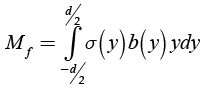 (1)
(1)
Where, y is the height of the cross section, b is the width, d is the diameter and σ is the normal stress. Figure 1 illustrates the normal stress distribution in the cross section of the shaft.
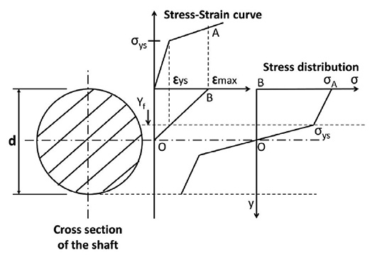
Figure 1. Normal stress distribution in the cross section of the shaft.
Source: Authors
In this case the cross section is circular, it can be shown that the width of the section in terms of height is given by Equation (2).
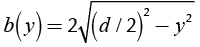 (2)
(2)
The normal stress, as a function of height, is a piecewise continuous and bounded function. The fact that it is a continuous piecewise function is due to the transition from elastic flow, determined by Hooke’s law, to plastic flow which can be approximated by the Ludwik equation (Lubliner, 2008); and it is bounded by 0 (no stress applied) and sut (ultimate strength). Then, the normal stress as a function of height is given by:
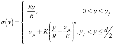 (3)
(3)
Where E is the Young modulus of the material, R is the average radius of curvature of the shaft in the cross-section analyzed (Where R ≠ ∞ due to shaft deflection), σys is the yield strength of the material, K is the strain hardening coefficient of the material, n is the strain hardening exponent of the material and yf is the height which divides the elastic and plastic region in the cross section.
On the other hand, once the shaft is deformed plastically, the stress-strain curve changes (Strain hardening - Cold work) and the new function σ’(y) has to be computed. The material tries to recover its original shape (This phenomenon is called “springback”). This recovery is approximately linear with a slope equal to the Young modulus of the material. Also the material suffers a strain hardening due to plastic deformation and the new yield stress σ’ys is equal to the strain that caused the deformation observed in the component. Figure 2 shows this process.
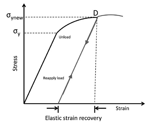
Figure 2. Plastic deformation, springback and strain hardening.
Source: Authors
Then, considering the new stress-strain curve, the new normal stress function σ’ is given by:
 (4)
(4)
Where R’ is the radius of curvature after deformation with stress level σ’ys and the load still applied, ε is the strain corresponding to σ’ys and R(y) is the radius of curvature of the shaft at height y. This latter term is also dependent on the variation of the stress σ’ but this is a function of y, then R ends a function of y.
Now, the values of R’ and ε have to be computed. The strain ε is determined using equation (5).
 (5)
(5)
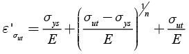
Where ε’ is the strain corresponding to the springback, and in this case it is given by:
 (6)
(6)
Now R’ can be calculated using Equation (7).
 (7)
(7)
The stress corresponding to R(y) = ∞ is denoted by σ1. It is important to take into account the material springback again, so an extra stress (overbending) has to be added, this extra stress is denoted by σ2. Figure 3 illustrates both stresses.
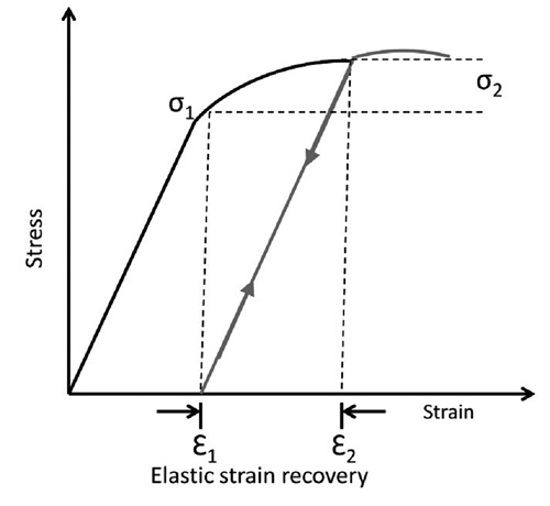
Figure 3. Stresses due to springback effect.
Source: Authors
Given that elastic strain recovery is approximately linear with a slope equal to the Young’s modulus and ε1 is the strain corresponding to R = ∞, then:
 (8)
(8)
Where ε2 can be obtained from Ludwik equation:
 (9)
(9)
Taking advantage of the symmetry for stress distribution and width of the cross section the equation for the bending moment Mf is given by:
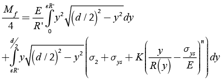 (10)
(10)
The goal is to know the bending moment Mf when R(y) approaches infinity. The integral is a Riemann series evaluated over a range in which the function to be integrated is uniformly continuous, then:
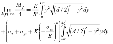 (11)
(11)
For the design of straightening machines is imperative to know the maximum force required to straighten a shaft. In order to compute the maximum force is necessary to define the maximum diameter dmax, the maximum length of the shaft Lmax and the maximum radius of curvature Rmax. The latter can be calculated as follows using Equation (12) and Equation (13):
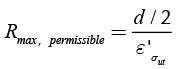 (12)
(12)
 (13)
(13)
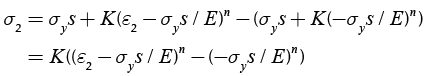
Finally, the maximum force required for a straightening process (this is the force the machine has to applied to the shaft) is given by:
 (14)
(14)
Results and discussion
To validate the model a case was selected. The material is the AISI 4340 steel. The stress-strain curve for this material is presented in the Atlas of Stress-Strain Curves (Atlas of Stress-Strain Curves, 2002). To determine the strain hardening coefficient K and the strain hardening exponent n for this steel a linear regression was used:
 (15)
(15)
Where, a0 and a1 are the unknown coefficients for the linear regression. Table 1 shows the data used in the regression.
Table 1. Linear regression data for AISI 4340 steel
|
ε |
σ (Mpa) |
In ε |
In σ |
|
0,01 |
1166,66667 |
-4,60517019 |
7,06190596 |
|
0,02 |
1216,66667 |
-3,91202301 |
7,10387016 |
|
0,03 |
1236,88889 |
-3,5065579 |
7,12035455 |
|
0,04 |
1261,11111 |
-3,21887582 |
7,13974844 |
|
0,05 |
1283,33333 |
-2,99573227 |
7,15721614 |
|
0,06 |
1290,33333 |
-2,81341072 |
7,16265586 |
Source: Atlas of Stress-Strain Curves, 2002
The results for K and n are 1515,55 MPa and 0,0567871, respectively. Table 2 resumes all data used.
Table 2. Data to test the model
|
dmax (mm) |
Lmax |
E |
σut (MPa) |
σys (MPa) |
K (MPa) |
n |
|
400 |
3 |
205 |
1300 |
1124 |
1515 |
0,057 |
Source: Authors
Finally, the maximum force required for this case is 11767 kN (1200 Ton). This force is in the range of power of the machines designed for this size (1000-3000 Ton).
Conclusions
A mathematical model was developed for straightening process of a bent shaft based on material behavior and geometric characteristics. The model uses the elasto-plastic mechanics of deformation. The model was validated with AISI 4340 steel which is a material highly used in machine elements. The maximum force calculated for this case is in the range of the applications for the geometric and material characteristics. This model is an important tool for design new straightening machines, and also to develop better reparation and maintenance techniques and processes. Future work should focus in more experimental data in order to adjust the model.
References
ASME International, 2002, Atlas of Stress-Strain Curves.
Jing, Y., Ding-Fei, Z., Xiao-Hong, W., Jian, P., and Lin, Y. (2013). The mathematic model of tension straightening process of magnesium alloy and experimental validation. Journal of Magnesium and Alloys 1:76-81. DOI: 10.1016/j.jma.2013.02.008.
Li, K., Chen, C., and Yang, S. (1999). Profile determination of a tube-straightening roller by envelope theory. Journal of Materials Processing Technology 94:157-166. DOI: 10.1016/S0924-0136(99)00089-8.
Lubliner, J., 2008, Plasticity Theory, Dover Publications, New York, pp. 81-82, Chap. 2.
Schleinzer, G., and Fischer, F. D. (2001). Residual stress formation during the roller straightening of railway rails. International Journal of Mechanical Sciences 43:2281-2295. DOI: 10.1016/S0020-7403(01)00041-8.
Seung-Cheol, K., and Sung-Chon, C. (2002). Synthesis of the multi-step straightness control system for shaft straightening process. Mechatronics 12:139-156. DOI: 10.1016/S0957-4158(00)00066-0.
Srimani, S. L., Pankaj, A. C., and Basu, J. (2005). Analysis of end straightness of rail manufacturing. International Journal of Mechanical Sciences 47:1874-1884. DOI: 10.1016/j.ijmecsci.2005.07.005.
Ugural, A., and Kenster, S. (1995). Advanced Strength and Applied Elasticity. New Jersey: Prentice-Hall , pp. 184-196, Chap. 5.
Wu, B. J., Chan, L. C., Lee, T. C., and Ao, L. W. (2000). A study on the precision modelling of the bars produced in two cross-roll straightening. Journal of Materials Processing Technology 99:202-206. DOI: 10.1016/S0924-0136(99)00421-5.

Attribution 4.0 International (CC BY 4.0) Share - Adapt
References
ASME International, 2002, Atlas of Stress-Strain Curves.
Jing, Y., Ding-Fei, Z., Xiao-Hong, W., Jian, P., and Lin, Y. (2013). The mathematic model of tension straightening process of magne-sium alloy and experimental validation. Journal of Magnesium and Alloys 1:76-81. DOI: 10.1016/j.jma.2013.02.008.
Li, K., Chen, C., and Yang, S. (1999). Profile determination of a tube-straightening roller roller by envelope theory. Journal of Materials Processing Technology 94:157-166. DOI: 10.1016/S0924-0136(99)00089-8.
Lubliner, J., 2008, Plasticity Theory, Dover Publications, New York, pp. 81-82, Chap. 2.
Schleinzer, G., and Fischer, F. D. (2001). Residual stress formation during the roller straightening of railway rails. International Journal of Mechanical Sciences 43:2281-2295. DOI: 10.1016/S0020-7403(01)00041-8.
Seung-Cheol, K., and Sung-Chon, C. (2002). Synthesis of the multi-step straightness control system for shaft straightening process. Mechatronics 12:139-156. DOI: 10.1016/S0957-4158(00)00066-0.
Srimani, S. L., Pankaj, A. C., and Basu, J. (2005). Analysis of end straightness of rail manufacturing. International Journal of Me-chanical Sciences 47:1874-1884. DOI: 10.1016/j.ijmecsci.2005.07.005.
Ugural, A., and Kenster, S. (1995). Advanced Strength and Applied Elasticity. New Jersey: Prentice-Hall , pp. 184-196, Chap. 5.
Wu, B. J., Chan, L. C., Lee, T. C., and Ao, L. W. (2000). A study on the precision modeling of the bars produced in two cross-roll straightening. Journal of Materials Processing Technology 99:202-206. DOI: 10.1016/S0924-0136(99)00421-5.
How to Cite
APA
ACM
ACS
ABNT
Chicago
Harvard
IEEE
MLA
Turabian
Vancouver
Download Citation
CrossRef Cited-by
1. Hong Lu, Yue Zang, Xinbao Zhang, Yongquan Zhang, Le Li. (2020). A General Stroke-Based Model for the Straightening Process of D-Type Shaft. Processes, 8(5), p.528. https://doi.org/10.3390/pr8050528.
2. Yue Zang, Hong Lu, Yongquan Zhang, Essa Alghannam, Zexing Guo, Le Li. (2019). A Straightness Control System for Motor Shaft Straightening with the Stroke Prediction Algorithm. 2019 6th International Conference on Systems and Informatics (ICSAI). , p.57. https://doi.org/10.1109/ICSAI48974.2019.9010553.
Dimensions
PlumX
Article abstract page views
Downloads


License
Copyright (c) 2017 Juan Camilo Galvis Salazar, Heriberto Enrique Maury Ramírez, Roque Julio Hernández Donado

This work is licensed under a Creative Commons Attribution 4.0 International License.
The authors or holders of the copyright for each article hereby confer exclusive, limited and free authorization on the Universidad Nacional de Colombia's journal Ingeniería e Investigación concerning the aforementioned article which, once it has been evaluated and approved, will be submitted for publication, in line with the following items:
1. The version which has been corrected according to the evaluators' suggestions will be remitted and it will be made clear whether the aforementioned article is an unedited document regarding which the rights to be authorized are held and total responsibility will be assumed by the authors for the content of the work being submitted to Ingeniería e Investigación, the Universidad Nacional de Colombia and third-parties;
2. The authorization conferred on the journal will come into force from the date on which it is included in the respective volume and issue of Ingeniería e Investigación in the Open Journal Systems and on the journal's main page (https://revistas.unal.edu.co/index.php/ingeinv), as well as in different databases and indices in which the publication is indexed;
3. The authors authorize the Universidad Nacional de Colombia's journal Ingeniería e Investigación to publish the document in whatever required format (printed, digital, electronic or whatsoever known or yet to be discovered form) and authorize Ingeniería e Investigación to include the work in any indices and/or search engines deemed necessary for promoting its diffusion;
4. The authors accept that such authorization is given free of charge and they, therefore, waive any right to receive remuneration from the publication, distribution, public communication and any use whatsoever referred to in the terms of this authorization.