Published
Isolated Converter for Power Factor Improvement in a Brushless DC Motor Driver
Convertidor Aislado para mejorar el Factor de Potencia en un Controlador de un Motor CD sin escobillas
DOI:
https://doi.org/10.15446/ing.investig.v37n3.62269Keywords:
Brushless DC Motor, Isolator Converter, Power Factor, Discontinuous Conduction Mode. (en)Motor CD Sin Escobillas, Convertidor Aislado, Factor de Potencia, Modo de Conducción Discontinuo (es)
El diseño y rendimiento del controlador se validan experimentalmente en un prototipo, a fi n de cumplir con el estándar internacional IEC 61000-3-2.
The main advantages of the Brushless Direct Current Motor (BLDCM) are high efficiency, low maintenance, long life, low noise, control simplicity, low weight, and compact construction. However, the traditional driver has power quality issues related to harmonic current injection and poor power factor. This paper presents an alternative for power factor improvement and harmonic content reduction, by means of an isolated converter that supplies the DC-AC voltage source inverter of a traditional BLDCM driver. The proposed converter operates in discontinuous-conduction mode. The design and performance of the driver are validated experimentally in a prototype, in order to comply with the IEC 61000-3-2 international standard.
Isolated Converter for Power Factor
Improvement in a Brushless DC Motor Driver
Convertidor Aislado para mejorar el Factor de Potencia
en un Controlador de un Motor CD sin escobillas
Alfonso A. Jiménez-Garibay 1, Juvenal Rodríguez-Reséndiz 2 , and Aurelio Domínguez-González 3
1Master of Sciences (looking forward Dr. Degree), Universidad Autónoma de Querétaro, Mexico. Affiliation: Member IEEE. E-mail: alonso.jimenez-garibay.1979@ieee.org
2Dr. in Engineering, Universidad Autónoma de Querétaro, Mexico. Affiliation: Senior Member IEEE. E-mail: juvenal@uaq.edu.mx
3Dr. in Engineering, Universidad Autónoma de Querétaro, Mexico. Affiliation: Member IEEE. E-mail: auregdz@uaq.edu.mx
How to cite: Jiménez-Garibay, A. A., Rodríguez-Reséndiz, J., Domínguez-González, A. (2017). Isolated Converter for Power Factor Improvement in a Brushless DC Motor Driver. Ingeniería e Investigación, 37(3), 52-60.
DOI: 10.15446/ing.investig.v37n3.62269.
ABSTRACT
The main advantages of the Brushless Direct Current Motor (BLDCM) are high efficiency, low maintenance, long life, low noise, control simplicity, low weight, and compact construction. However, the traditional driver has power quality issues related to harmonic current injection and poor power factor. This paper presents an alternative for power factor improvement and harmonic content reduction, by means of an isolated converter that supplies the DC-AC voltage source inverter of a traditional BLDCM driver. The proposed converter operates in discontinuous-conduction mode. The design and performance of the driver are validated experimentally in a prototype, in order to comply with the IEC 61000-3-2 international standard.
Keywords: Brushless DC Motor, Isolator Converter, Power Factor, Discontinuous Conduction Mode.
RESUMEN
Las principales ventajas de un motor de CD sin escobillas son su alta eficiencia, poco mantenimiento, larga vida útil, bajo ruido, simplicidad en el control, bajo peso y una construcción compacta. Sin embargo, el controlador tradicional tiene problemas de calidad de la energía relacionados con la inyección de corrientes armónicas y pobre factor de potencia. Este artículo presenta una alternativa para mejorar este aspecto y reducir el contenido armónico mediante un convertidor aislado que alimenta un inversor de voltaje CD-CA de un controlador tradicional para un BLDCM; el convertidor propuesto opera en modo de conducción discontinuo. El diseño y rendimiento del controlador se validan experimentalmente en un prototipo, a fin de cumplir con el estándar internacional IEC 61000-3-2.
Palabras clave: Motor CD Sin Escobillas, Convertidor Aislado, Factor de Potencia, Modo de Conducción Discontinuo.
Received: January 27th 2017
Accepted: July 18th 2017
Introduction
In recent years, the use of Brushless DC Motors in automotive, medical, robotics, aerospace, and automation applications has been increasing, due to performance improvements such as efficiency, torque speed ratio, dynamics response, and speed ranges (Gieras, 2002; Krause, Wasynczuk, & Sudhoff, 2002).
The electronic switching waveforms needed to supply the BLDCM windings of a traditional driver requires the use of an energy conversion from AC to DC and DC to AC to generate the correct sequence (Xia, 2012), including the position of the rotor via sensor or sensorless techniques (Bist & Singh, 2014c; Gamazo-Real, Vázquez-Sánchez, & Gómez-Gil, 2010; Kim, Lee, & Ehsani, 2005). From a power quality perspective, the AC-DC-AC traditional converter shown in Figure 1 generates a high harmonic content due to the way the driver demands current from the power supply, resulting in poor power factor (Singh & Singh, S., 2010).
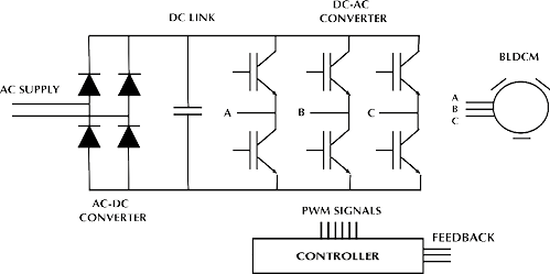
Figure 1. Traditional AC-DC-AC non-isolated driver for BLDC motor without PFC.
Source: Authors
By considering this problem, the energy conversion process is modified by introducing an intermediate stage of DC-DC conversion, typically a boost-based converter (Pereira, Da Silva, Silva, & Tofoli, 2015), which improves power factor and reduces harmonic content, as shown in Figure 2. When speed control is performed directly in the DC-AC conversion stage in a traditional driver, switching losses are generated due to the efforts of the semiconductor switches (Yen-Shin, Fu-San, & Yung-Hsin, 2004). The inclusion of an intermediate stage not only helps improve power factor but also allows control of BLDCM speed, which results in reduced switching losses since the DC-AC converter operates at the fundamental frequency.
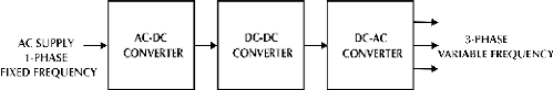
Figure 2. Energy conversion process with a DC-DC conversion stage.
Source: Authors
The BLDCM drivers that offer power factor improvements can be categorized as non-isolated PFC (Power Factor Correction), isolated PFC, bridgeless non-isolated PFC, bridgeless isolated PFC, and high-quality rectifiers (Singh, 2014; Singh & Bist, 2013).
For non-isolated PFC BLDCM drivers, literature has reported several proposals of intermediate stages with particular characteristics. By 2016, an analysis of SEPIC and CUK was presented (Crisbin & Sasikumar, 2016), all of them operating in DCM (Discontinuous Conduction Mode). In 2014, an alternative was presented by using a canonical switching cell operating in CCM (Continuous Conduction Mode) and DCM (Bist & Singh, 2014a). The aforementioned BLDCM drivers achieve unitary power factor due to their voltage follower behavior and are in compliance with the IEC 61000-3-2 standard (“Limits for harmonic current emissions (equipment input current ≤16 A per phase),” 2000), with a minimum of components. However, these do not provide galvanic isolation.
In the case of the isolated PFC BLDCM driver category, literature has reported the following DC-DC intermediate stages. The first alternative uses a Sheppard-Taylor converter with a triple-DCM; the converter consists of a single transformer, two switches (two PWM control signals), an inductor, two capacitors, and four diodes (Singh & Bist, 2015). The second alternative uses a boost-forward single-stage isolated power-factor-corrected power supply (SSIPP); the isolated cell converter has a transformer with two primary windings connected in parallel, a single switch, two inductors, two capacitors, and five diodes (Bist & Singh, 2014b). Both drivers comply with the IEC 61000-3-2 standard and achieve unity power factor. Thus, the evaluation of each alternative depends on the application requirements in relation to power factor improvement or correction, the number of components involved at the DC-DC intermediate stage, and the galvanic isolation.
This paper presents an alternative for power factor improvement of a traditional BLDCM driver, by the inclusion of a single-sensor isolated DC-DC converter operating in discontinuous conduction mode. The main advantage, in comparison with other isolated PFC alternatives, is the compromise between the number of components (sensors, passive, and active components) and the power factor improvement.
Proposed converter and operating modes
Figure 3 shows the proposed intermediate stage, which incorporates an auxiliary winding interconnected to the primary winding of a high-frequency transformer, to provide feedback of recycled power into the input converter to shape the current demanded by the DC-AC stage. This operating mode is a function of the polarization of the auxiliary diode (Daux).
The proposed converter presents three operation modes that depend on the commutation of the main switch (S1).
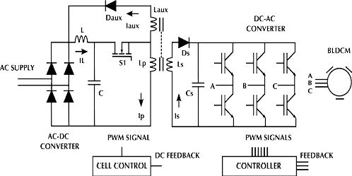
Figure 3. Proposed isolated single-sensor converter for power factor improvement.
Source: Authors
Figure 4 shows the first operating mode, in which the main switch is turned off, the input inductor (L) is completely discharged and the secondary inductor of the transformer (Ls) discharges energy through the output capacitor (Cs). At this moment, the current (iaux) is equal to zero, and the input inductor current (iL) demands energy from the power supply.
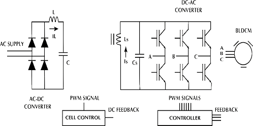
Figure 4. First operating mode - the main switch is turned off.
Source: Authors
Analyzing the circuit in steady state, while the main switch condition is turned-off, the demand from the power supply takes a triangular shape with a width equal to the product of the input voltage (VAC ) and the input inductor current, so it is possible to set the input power (1) as
 (1)
(1)
Where (2) expressed the off-time given by
 (2)
(2)
Replacing (2) in (1), the input power (3) is equal to
 (3)
(3)
From (3), it is possible to infer that, if the input inductor current is constant for each instant of time, the power waveform will depend on the input voltage and the DC bus voltage (VC).
Figure 5 shows the second operating mode, in which the main switch remains in a turned-off condition; the energy in the input inductor is totally discharged, and the converter does not demand energy from the power supply.
The power factor improvement is largely due to the amount of energy returned to the input through the auxiliary winding interconnected to the primary winding of the transformer.
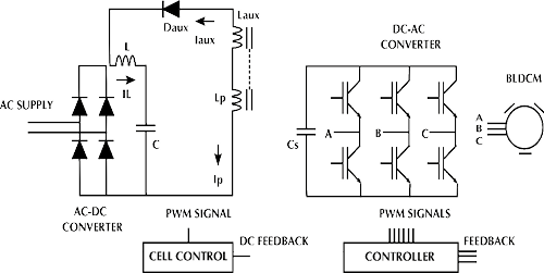
Figure 5. Second operating mode - the main switch remains in a turned-off condition.
Source: Authors
The final operating mode is shown in Figure 6 ; the main switch changes to a turned-on condition. The result is an energy charge into the input inductor and the primary inductor (LP) of the transformer. For this instance, the input inductor current is equal to the auxiliary current; at this time, the converter does not demand energy from the power supply.
Theoretical design
Establishing in (4) a relationship between the number of turns and voltage in the primary and auxiliary windings (Np,Naux, Vp,Vaux) during the  condition.
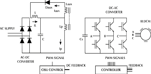
Figure 6. Third operating mode - main switch in a turned-on condition.
Source: Authors
 (4)
(4)
Assuming that the primary voltage is equal to the DC-link voltage in the capacitor (C). Solving for the auxiliary voltage, the transformation ratio (n) is represented in (5) as
 (5)
(5)
Duty cycle for DCM
The peak current of the input inductor (iLon−pk) for on-time is defined in (6) as follows
 (6)
(6)
Therefore, the average current (iLon) in (7) is expressed as
 (7)
(7)
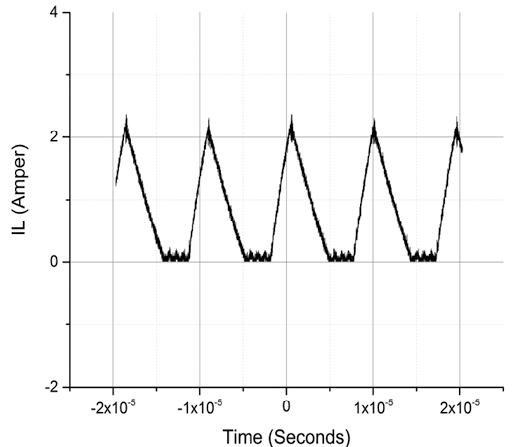
Considering that the peak current in the input inductor has a triangular geometry as shown in Figure 7 , the average current in (8) is
 (8)
(8)
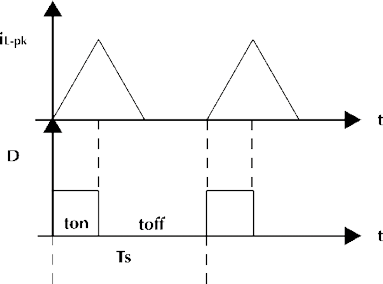
Figure 7. Input inductor current waveform in DCM.
Source: Authors
Performing the same analysis, but now for off-time for the second operating stage, the current peak of the input inductor (iLoff−pk) is obtained in (9)
 (9)
(9)
Then in (10), the average current of the input inductor (iLoff) is
 (10)
(10)
Replacing (9) into (10) and solving the expression, the average current during off-time is obtained in (11)
 (11)
(11)
As the peak current in the input inductor is the same for on-time and off-time in (6) and (9), then in (12) the equality is defined as
 (12)
(12)
Solving for duty cycle at off-time in (13)
 (13)
(13)
In (14) is defined the condition to ensure discontinuity in the input inductor
 (14)
(14)
Replacing duty cycle at off-time, and solving in (15) for duty cycle at on-time
 (15)
(15)
Energy balance
Figure 8
shows the power flowchart. The amount of recycled energy ( ) in half cycle of AC supply is defined in (16) as
 (16)
(16)
And the input power in (17) is given by
 (17)
(17)
Substituting (11) into (17) and solving in (18)
 (18)
(18)
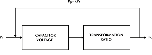
Figure 8. Power flowchart.
Source: Authors
From the energy balance, in (19) the percentage of recycled energy (K), is defined by
 (19)
(19)
Substituting and solving in (20) for the percentage of recycled energy
 (20)
(20)
Applying an energy balance in the high-frequency transformer, the expression (21) for the primary winding of the proposed converter is a function of the output power (Po), and the switching period (TS) given by
 (21)
(21)
Thus, the auxiliary winding (22) is
 (22)
(22)
Considering the time in which the input power is equal to the output power and solving for the duty cycle at (23)
 (23)
(23)
Substituting the duty cycle in the inequality that ensures current discontinuity and solving in (24) for the input inductor
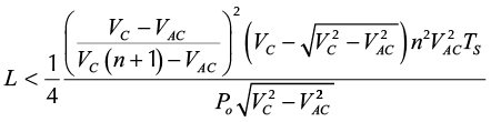 (24)
(24)
Design procedure
The proposed design procedure is summarized in the following steps:
- Defining the maximum duty cycle to ensure the discontinuous operating mode in the input inductor and the high frequency transformer
- Finding the value of the input inductor by performing an energy balance
- Establishing the amount of recycled energy returned to the power input
- Calculating the secondary winding of the high frequency transformer, as a function of the desired output power
- Calculating the auxiliary and primary windings
Experimental results
The proposed design procedure was implemented in an experimental prototype drive for a brushless motor model BLM-N23-50-1000-B; Table 1 presents the BLDCM specifications.
Table 1. BLDCM specifications
|
Parameter |
Unit |
BLM-N23-50-1000-B |
|
Kt–Torque Constant |
Nm/A |
0.08 |
|
Tc–Continuous Torque |
Nm |
0,39 |
|
Tp–Peak Torque |
Nm |
0,83 |
|
Jm–Moment of Inertia |
kg * m2 |
25u |
|
Recommended Supply Voltage |
volts |
48 |
|
wm–Maximum Speed |
rpm |
5000 |
|
R–Armature Resistance |
ohm |
1.2 |
|
L–Armature Inductance |
H |
2,6m |
|
Tm–Electro-mechanical Time Constant |
sec |
4,5m |
|
Encoder Resolution |
lines/rev |
1000 |
Source: Authors
The implementation was conducted according to the design procedure of section 4; Table 2 shows the resulting design values.
Table 2. Proposed converter design values
|
Unit |
Value |
|
|
VAC – Input voltage |
AC volts |
120 |
|
Vo – Output Voltage |
DC volts |
48 |
|
Ts – Switching period |
sec |
10 u |
|
L – Input inductor |
H |
190 u |
|
Unit |
Value |
|
|
Lp – Primary winding |
H |
418 u |
|
Ls – Secondary winding |
H |
17 u |
|
Laux – Auxiliary winding |
H |
268 u |
|
C – DC bus capacitor |
F |
100 u / 400 V |
|
Co – Output capacitor |
F |
47 u / 100 V |
Source: Authors
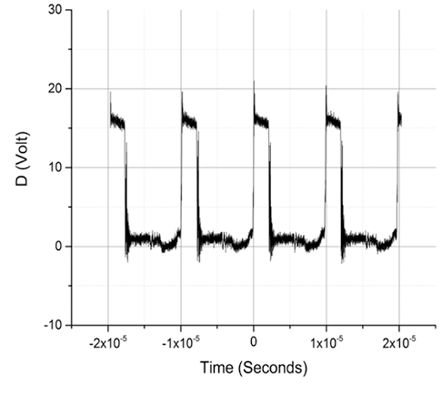
An important step is to define the maximum duty cycle at rated power, in this specific case, a 31% of the duty cycle is the maximum value to keep the DCM in the input inductor as shown in Figure 9 . If duty cycle exceeds this value, the discontinuous mode becomes continuous mode and changes the converter behavior.
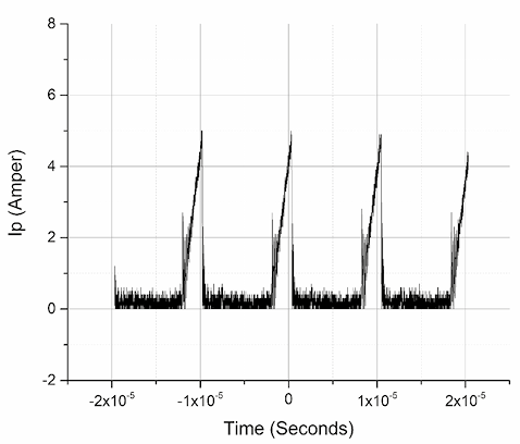
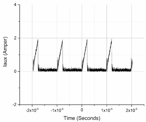
Figure 10 shows the discontinuous transformer current of the primary, secondary, and auxiliary windings at a frequency of 100 KHz and duty cycle of 31%.
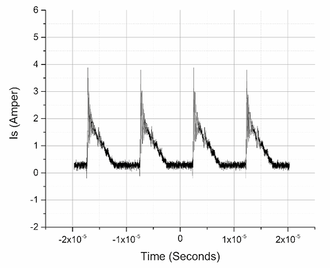
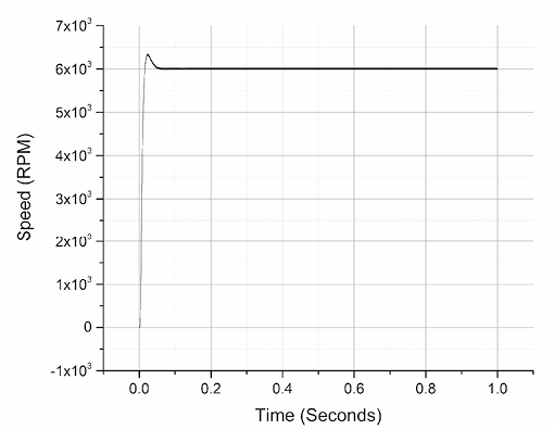
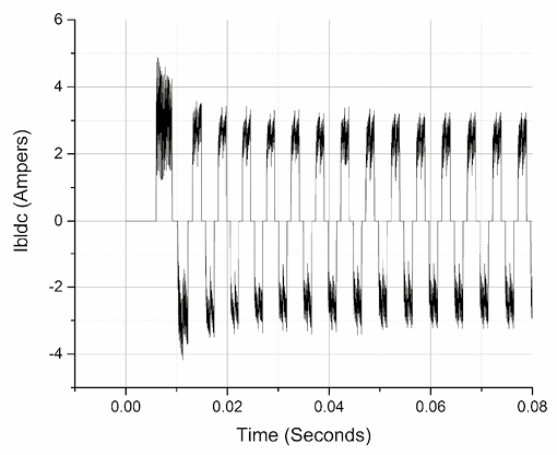
The duty cycle is also related to the output voltage of the proposed converter, at 31%, the output voltage is equal to 48 VDC that supplies the DC-AC converter. Figure 11 shows the parameters associated with the performance evaluation of the BLDC driver such as speed, BLDC voltage and current per phase, and phase control signal based on six-step or 120 degrees technique. The dynamic response takes approximately 0.06 Seconds to stabilize the speed RPMs, and the increase of the BLDC current verify the operation. A well-known advantage of using an intermediate DC-DC conversion is that the DC-AC converter is used only for electronic commutation, with a low switching frequency operation that reduces the switching losses. The control is based on a typical PWM with a double PI compensator and setpoint at 6000 RPMs.
a.
b.
Figure 9. DCM operation mode; (a) Discontinuous current of the input inductor; (b) PWM signal control at 31 %.
Source: Authors
a.
b.
c.
Figure 10. High-frequency DCM current waveforms of the proposed transformer; (a) Primary winding; (b) Secondary winding; (c) Auxiliary winding.
Source: Authors
a.
b.
c.
Figure 11. BLDC driver performance waveforms; (a) Rotor speed; (b) BLDC winding current; and (c) Phase control signal.
Source: Authors
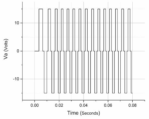
The implementation of the experimental prototype is based on a 3-phase DC-AC converter based on IGBT semiconductors. Figure 12 shows a comparison of AC input waveforms. The first waveform is the power supply voltage. The second waveform belongs to the proposed converter, where, although it does not present a unity power factor. It is significantly improved in 98% the power factor and 18% the harmonic content, and the third waveform draws the current demanded from the power supply by a traditional driver, which has a low power factor. Figure 13 shows a comparative bar graph of harmonic current and the standard IEC 61000-3-2 Class A, where it can be seen that the proposed converter meets the requirements.
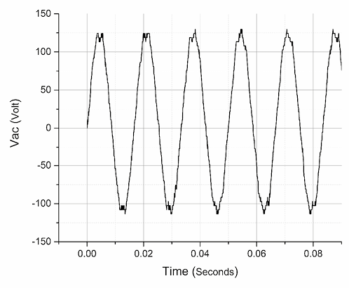
a.
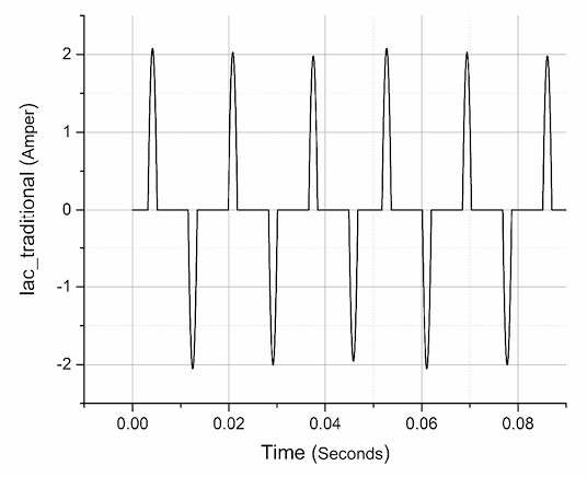
b.
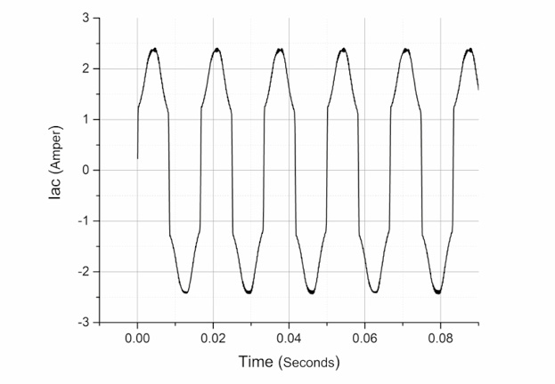
c.
Figure 12. Comparison of AC input waveforms; (a) Power supply voltage; (b) Traditional driver current draw; and (c) Proposed driver current draw.
Source: Authors
An important feature is that the speed control is a function of the DC output of the proposed isolated converter, this represents low losses in the IGBTs full-bridge due to fundamental switching; in comparison with a traditional and traditional PFC converters in which the DC bus is fixed and the speed control depend on the DC-AC converter directly. Table 3 shows an evaluation of features related to speed control regulation, 3-phase DC-AC inverter control, DC-DC converter control, BLDCM sensors, close loop DC-DC converter feedback sensor, DC-AC converter losses, power factor improvement, and galvanic isolation.

Figure 13. Comparison of harmonic current limit; proposed BLDC converter and IEC 61000-3-2 Class A.
Source: Authors
Table 3. Feature comparison: Traditional, Traditional PFC, and the proposed driver
|
Features |
Traditional |
Traditional PFC |
Proposed driver |
|
Speed control |
---- |
No |
Yes |
|
BLDCM control |
Complex |
Complex |
Simple |
|
DC-DC converter control |
---- |
DCM |
DCM |
|
BLDCM sensors |
Current & Hall effect |
Current & Hall effect |
Hall effect |
|
DC-DC converter sensor |
---- |
Voltage |
Voltage |
|
DC-AC converter losses |
High |
High |
Low |
|
Power factor |
Poor |
High |
High |
|
Galvanic isolation |
No |
No |
Yes |
Source: Authors
Table 4. Component number comparison for isolated PFC BLDCM drivers
|
Converter |
Sw |
D |
L |
T |
C |
Total |
|
Sheppard-Taylor |
2 |
8 |
2 |
1 |
3 |
14 |
|
Boost-Forward |
1 |
8 |
2 |
1 |
3 |
13 |
|
Proposed |
1 |
6 |
1 |
1 |
2 |
11 |
Source: Authors
Table 4 presents a component number comparison of two isolated BLDC drivers versus the proposed converter. Herein, Sw is the number of switching controlled semiconductor, D is the number of diodes (high recovery and low-cost power diodes), L is the number of inductors, T is the number of high-frequency transformers, and C is the number of capacitors.
Finally, Figure 14 shows the experimental prototype of the proposed BLDC driver. The AC-DC converter used RM type cores for the construction of the input inductor and transformer, a single-ended PWM generator at 100 KHz, and an analog gate driver for the MOSFET semiconductor. The DC-AC converter has a single-phase AC-DC module to create a 24 VDC bus, in order to supply four DC-DC isolated step down of 24 to 15 VDC for the optocoupler stage used to drive the IGBT module and a microcontroller to embed a 120° technique for the switching sequence at fundamental frequency.
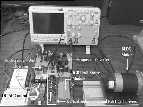
Figure 14 Experimental prototype.
Source: Authors
Conclusions
An isolated DC-DC converter for supplying the DC-AC in a BLDCM driver has been designed to improve the power factor at the power supply for low-power applications. BLDCM rotor speed is controlled by a single voltage sensor in the DC-link, which allows the DC-AC converter to operate at fundamental frequency reducing switching losses. Three operation modes in DCM have been explained and a design procedure has been proposed. Finally, the isolated DC-DC converter prototype has shown an acceptable performance with a power factor of 98%, a total harmonic distortion of 18%, and a reduced number of components in comparison with related work.
References
Bist, V., & Singh, B. (2014a). A PFC-Based BLDC Motor Drive Using a Canonical Switching Cell Converter. Industrial Informatics, IEEE Transactions on, 10(2), 1207-1215.
DOI: 10.1109/TII.2014.2305620
Bist, V., & Singh, B. (2014b). Power factor correction in brushless DC motor drive using a boost-forward SSIPP. Paper presented at the India Conference (INDICON), 2014 Annual IEEE.
Bist, V., & Singh, B. (2014c). Power factor correction in sensorless BLDC motor drive. Paper presented at the Power Electronics (IICPE), 2014 IEEE 6th India International Conference on.
Crisbin, P., & Sasikumar, M. (2016). Analysis of PFC cuk and PFC sepic converter based intelligent controller fed BLDC motor drive. Paper presented at the 2016 Second International Conference on Science Technology Engineering and Management (ICONSTEM).
Gamazo-Real, J. C., Vázquez-Sánchez, E., & Gómez-Gil, J. (2010). Position and Speed Control of Brushless DC Motors Using Sensorless Techniques and Application Trends. Sensors, 10(7), 6901.
Gieras, J. F. (2002). Permanent magnet motor technology: design and applications: CRC press.
Kim, T.-H., Lee, H.-W., & Ehsani, M. (2005). State of the art and future trends in position sensorless brushless DC motor/generator drives. Paper presented at the Industrial Electronics Society, 2005. IECON 2005. 31st Annual Conference of IEEE.
Krause, P., Wasynczuk, O., & Sudhoff, S. (2002). Theory of Brushless dc Machines Analysis of Electric Machinery and Drive Systems (pp. 261-282): Wiley-IEEE Press.
Pereira, D. D. C., Da Silva, M. R., Silva, E. M., & Tofoli, F. L. (2015). Comprehensive review of high power factor ac-dc boost converters for PFC applications. International Journal of Electronics, 102(8), 1361-1381.
DOI: 10.1080/00207217.2014.981871
Singh, B. (2014). Power quality improvements in permanent magnet brushless DC motor drives for home appliances. Paper presented at the Industrial and Information Systems (ICIIS), 2014 9th International Conference on.
Singh, B., & Bist, V. (2013). A Reduced Sensor Power Factor Corrected Bridgeless Flyback Converter Fed Brushless DC Motor Drive. Electric Power Components and Systems, 41(11), 1114-1128. DOI: 10.1080/15325008.2013.809821
Singh, B., & Bist, V. (2015). An Improved Power Quality Based Sheppard–Taylor Converter Fed BLDC Motor Drive. Journal of The Institution of Engineers (India): Series B, 96(4), 327-337. DOI: 10.1007/s40031-014-0152-6
Singh, B., & Singh, S. (2010). Single-phase power factor controller topologies for permanent magnet brushless DC motor drives. Power Electronics, IET, 3(2), 147-175.
DOI: 10.1049/iet-pel.2008.0313
Xia, C.-l. (2012). Permanent magnet brushless DC motor drives and controls: John Wiley & Sons.
Yen-Shin, L., Fu-San, S., & Yung-Hsin, C. (2004). Novel loss reduction pulsewidth modulation technique for brushless dc motor drives fed by MOSFET inverter. Power Electronics, IEEE Transactions on, 19(6), 1646-1652.
DOI: 10.1109/TPEL.2004.836626

Attribution 4.0 International (CC BY 4.0) Share - Adapt
References
Bis t, V., & Singh, B. (2014a). A PFC-Based BLDC Motor Drive Using a Canonical Switching Cell Converter. Industrial Informatics, IEEE Transactions on, 10(2), 1207-1215. DOI: 10.1109/TII.2014.2305620
Bis t, V., & Singh, B. (2014b). Power factor correction in brushless DC motor drive using a boost-forward SSIPP. Paper presented at the India Conference (INDICON), 2014 Annual IEEE
Bist, V., & Singh, B. (2014c). Power factor correction in sensorless BLDC motor drive. Paper presented at the Power Electronics (IICPE), 2014 IEEE 6th India International Conference on.
Crisbin, P., & Sasikumar, M. (2016). Analysis of PFC cuk and PFC sepic converter based intelligent controller fed BLDC motor drive. Paper presented at the 2016 Second International Conference on Science Technology Engineering and Management (ICONSTEM).
Gamazo-Real, J. C., Vázquez-Sánchez, E., & Gómez-Gil, J. (2010). Position and Speed Control of Brushless DC Motors Using Sensorless Techniques and Application Trends. Sensors, 10(7), 6901.
Gieras, J. F. (2002). Permanent magnet motor technology: design and applications: CRC press.
Kim, T.-H., Lee, H.-W., & Ehsani, M. (2005). State of the art and future trends in position sensorless brushless DC motor/generator drives. Paper presented at the Industrial Electronics Society, 2005. IECON 2005. 31st Annual Conference of IEEE.
Krause, P., Wasynczuk, O., & Sudhoff, S. (2002). Theory of Brushless dc Machines Analysis of Electric Machinery and Drive Systems (pp. 261-282): Wiley-IEEE Press.
Pereira, D. D. C., Da Silva, M. R., Silva, E. M., & Tofoli, F. L. (2015). Comprehensive review of high power factor ac-dc boost converters for PFC applications. International Journal of Electronics, 102(8), 1361-1381. DOI: 10.1080/00207217.2014.981871
Singh, B. (2014). Power quality improvements in permanent magnet brushless DC motor drives for home appliances. Paper presented at the Industrial and Information Systems (ICIIS), 2014 9th International Conference on.
Singh, B., & Bist, V. (2013). A Reduced Sensor Power Factor Corrected Bridgeless Flyback Converter Fed Brushless DC Motor Drive. Electric Power Components and Systems, 41(11), 1114-1128. DOI: 10.1080/15325008.2013.809821
Singh, B., & Bist, V. (2015). An Improved Power Quality Based Sheppard–Taylor Converter Fed BLDC Motor Drive. Journal of The Institution of Engineers (India): Series B, 96(4), 327- 337. DOI: 10.1007/s40031-014-0152-6
Singh, B., & Singh, S. (2010). Single-phase power factor controller topologies for permanent magnet brushless DC motor drives. Power Electronics, IET, 3(2), 147-175. DOI: 10.1049/iet-pel.2008.031
Xia, C.-l. (2012). Permanent magnet brushless DC motor drives and controls: John Wiley & Sons.
Yen-Shin, L., Fu-San, S., & Yung-Hsin, C. (2004). Novel loss reduction pulsewidth modulation technique for brushless dc motor drives fed by MOSFET inverter. Power Electronics, IEEE Transactions on, 19(6), 1646-1652. DOI: 10.1109/TPEL.2004.836626
How to Cite
APA
ACM
ACS
ABNT
Chicago
Harvard
IEEE
MLA
Turabian
Vancouver
Download Citation
CrossRef Cited-by
Dimensions
PlumX
Article abstract page views
Downloads


License
Copyright (c) 2017 Alfonso A Jimenez-Garibay, Juvenal Rodríguez-Reséndiz, Aurelio Domínguez-González

This work is licensed under a Creative Commons Attribution 4.0 International License.
The authors or holders of the copyright for each article hereby confer exclusive, limited and free authorization on the Universidad Nacional de Colombia's journal Ingeniería e Investigación concerning the aforementioned article which, once it has been evaluated and approved, will be submitted for publication, in line with the following items:
1. The version which has been corrected according to the evaluators' suggestions will be remitted and it will be made clear whether the aforementioned article is an unedited document regarding which the rights to be authorized are held and total responsibility will be assumed by the authors for the content of the work being submitted to Ingeniería e Investigación, the Universidad Nacional de Colombia and third-parties;
2. The authorization conferred on the journal will come into force from the date on which it is included in the respective volume and issue of Ingeniería e Investigación in the Open Journal Systems and on the journal's main page (https://revistas.unal.edu.co/index.php/ingeinv), as well as in different databases and indices in which the publication is indexed;
3. The authors authorize the Universidad Nacional de Colombia's journal Ingeniería e Investigación to publish the document in whatever required format (printed, digital, electronic or whatsoever known or yet to be discovered form) and authorize Ingeniería e Investigación to include the work in any indices and/or search engines deemed necessary for promoting its diffusion;
4. The authors accept that such authorization is given free of charge and they, therefore, waive any right to receive remuneration from the publication, distribution, public communication and any use whatsoever referred to in the terms of this authorization.