Published
Dynamic analysis of three autoventilated disc brakes
Análisis dinámico de tres frenos de disco autoventilados
DOI:
https://doi.org/10.15446/ing.investig.v37n3.63381Keywords:
Dynamics, friction, FEA, CFD, disc brakes, automobile (en)Dinámica, fricción, FEA, CFD, frenos de disco, automóvil (es)
The braking system of a car must meet several requirements, among which safety is the most important. It is also composed of a set of mechanical parts such as springs, different types of materials (Metallic and Non Metallic), gases and liquids. The brakes must work safely and predictably in all circumstances, which means having a stable level of friction, in any condition of temperature, humidity and salinity of the environment. For a correct design and operation of brake discs, it is necessary to consider different aspects, such as geometry, type of material, mechanical strength, maximum temperature, thermal deformation, cracking resistance, among others. Therefore, the main objective of this work is to analyze the dynamics and kinetics of the brake system from the pedal as the beginning of mathematical calculations to simulate the behavior and Analysis of Finite Elements (FEA), with the help of SolidWorks Simulation Software. The results show that the third brake disc works best in relation to the other two discs in their different working conditions such as speed and displacement in braking, concluding that depending on the geometry of the brake and the cooling channels these systems can be optimized that are of great importance for the automotive industry.
El sistema de frenado de un automóvil debe satisfacer varios requerimientos, entre los cuales, la seguridad es el más importante. Además, está compuesto por un conjunto de piezas mecánicas tales como: resortes, diferentes tipos de materiales (Metálicos y No Metálicos), gases y líquidos. Los frenos deben trabajar en forma segura y predecible en cualquier circunstancia, lo cual implica disponer de un nivel estable de fricción en cualquier condición de temperatura, humedad y salinidad del medio ambiente. Para un correcto diseño y operación de los discos de freno, es necesario considerar diferentes aspectos, tales como la geometría, el tipo de material, la resistencia mecánica, la temperatura máxima, la deformación térmica, la resistencia al agrietamiento, entre otros. Por lo anterior, el principal objetivo de este trabajo es analizar la dinámica y la cinética del sistema de freno a partir del pedal como inicio de los cálculos matemáticos para simular el comportamiento en mediante el Análisis de Elementos Finitos (FEA), con la ayuda del Software SolidWorks Simulation. Los resultados demuestran que el disco de freno número tres funciona mejor con relación a los otros dos discos en sus diferentes condiciones de trabajo, como lo son velocidad y desplazamiento en frenado. Así, se concluye que dependiendo de la geometría del freno y de los canales de refrigeración, se pueden optimizar estos sistemas de gran importancia para la industria automotriz.
Dynamic analysis of three autoventilated disc brakes
Análisis dinámico de tres frenos de disco autoventilados
Ricardo A. García-León 1, and Eder Flórez-Solano 2
1Mechanical Engineer, Universidad Francisco de Paula Santander, Ocaña, Colombia. M.Sc. Industrial Engineer. Affiliation: Auxiliar professor, Faculty of Engineering, Universidad Francisco de Paula Santander, Ocaña, Colombia. Member of INGAP Research Group. E-mail: ragarcial@ufpso.edu.co
2Mechanical Engineer, Universidad Francisco de Paula Santander, Ocaña, Colombia. Ph.D.(c). M.Sc. Mechanical Engineer. Affiliation: Auxiliar professor, Faculty of Engineering, Universidad Francisco de Paula Santander, Ocaña, Colombia. Member of INGAP Research Group. E-mail: enflorezs@ufpso.edu.co
How to cite: García-León, R. A., Flórez-Lozano, E. (2017). Dynamic analysis of three autoventilated disc brakes. Ingeniería e Investigación, 37(3), 102-114.
DOI: 10.15446/ing.investig.v37n3.63381.
ABSTRACT
The braking system of a car must meet several requirements, among which safety is the most important. It is also composed of a set of mechanical parts such as springs, different types of materials (Metallic and Non Metallic), gases and liquids. The brakes must work safely and predictably in all circumstances, which means having a stable level of friction, in any condition of temperature, humidity and salinity of the environment. For a correct design and operation of brake discs, it is necessary to consider different aspects, such as geometry, type of material, mechanical strength, maximum temperature, thermal deformation, cracking resistance, among others. Therefore, the main objective of this work is to analyze the dynamics and kinetics of the brake system from the pedal as the beginning of mathematical calculations to simulate the behavior and Analysis of Finite Elements (FEA), with the help of SolidWorks Simulation Software. The results show that the third brake disc works best in relation to the other two discs in their different working conditions such as speed and displacement in braking, concluding that depending on the geometry of the brake and the cooling channels these systems can be optimized that are of great importance for the automotive industry.
Keywords: Dynamics, friction, FEA, CFD, disc brakes, automobile.
RESUMEN
El sistema de frenado de un automóvil debe satisfacer varios requerimientos, entre los cuales, la seguridad es el más importante. Además, está compuesto por un conjunto de piezas mecánicas tales como: resortes, diferentes tipos de materiales (Metálicos y No Metálicos), gases y líquidos. Los frenos deben trabajar en forma segura y predecible en cualquier circunstancia, lo cual implica disponer de un nivel estable de fricción en cualquier condición de temperatura, humedad y salinidad del medio ambiente. Para un correcto diseño y operación de los discos de freno, es necesario considerar diferentes aspectos, tales como la geometría, el tipo de material, la resistencia mecánica, la temperatura máxima, la deformación térmica, la resistencia al agrietamiento, entre otros. Por lo anterior, el principal objetivo de este trabajo es analizar la dinámica y la cinética del sistema de freno a partir del pedal como inicio de los cálculos matemáticos para simular el comportamiento en mediante el Análisis de Elementos Finitos (FEA), con la ayuda del Software SolidWorks Simulation. Los resultados demuestran que el disco de freno número tres funciona mejor con relación a los otros dos discos en sus diferentes condiciones de trabajo, como lo son velocidad y desplazamiento en frenado. Así, se concluye que dependiendo de la geometría del freno y de los canales de refrigeración, se pueden optimizar estos sistemas de gran importancia para la industria automotriz.
Palabras clave: Dinámica, fricción, FEA, CFD, frenos de disco, automóvil.
Received: March 17th 2017
Accepted: August 14th 2017
Introduction
The braking system is, undoubtedly, the most important component in automobiles for road safety because of slowing and stopping of the vehicle and so, consequently, the safety of the vehicle passengers depend on this system. Generally, 70 % of the kinetic energy of the vehicle is absorbed by the front brakes, and the remainder is absorbed by the rear brakes. On most automobiles, the front wheels have disc brakes and the rear wheels have drum brakes. Friction is used to reduce the speed of the vehicle, where the friction is generated by hydraulic pressure that presses the brake pads against the cast iron discs. The brakes convert the vehicle kinetic energy to heat energy during braking, and the temperature of the brakes increases with the amount of friction. This heat dissipates rapidly to the surrounding air by convection (heat transfer between masses at different temperatures). The heat dissipation depends on the geometry of the disc and on the material. Environmental factors also affect the heat transfer. However, high heat accelerates corrosion. At high temperatures, radiation heat transfer occurs, which also dissipates the heat stored in the disk (García-León, Acosta Pérez, & Flórez Solano, 2015; Hirasawa, Kawanami, & Shirai, 2014). Under these conditions, the functionality and the safety of the brakes can be compromised.
The geometry of the disks is chosen based on the load capacity and the operation of the vehicle, which is an important factor in the initial design phase. The discs should be designed to avoid overheating due to friction, taking into account the physical, mechanical and chemical properties. In certain cases, the materials selected may have properties that have negative effects on the braking efficiency (Bocîi, 2011). In designing ventilated disc brakes, it is very important to analyze the behavior of the surrounding fluid (air). The characteristics and the flow of the fluid at the surface of the disc can be studied to evaluate the effectiveness of the brakes and the heat dissipation by the disc surface and the ventilation channels (Yan, Feng, Yang, & Lu, 2015). The heat dissipation and the performance of ventilated disc brakes depend largely on the air flow over the surface and through the ventilation channels of the discs, which can be studied using computational fluid dynamics (CFD). The design software SolidWorks offers modules for CFD analysis (Chi, He, & Naterer, 2009; Klimenda, Soukup, & Kampo, 2016; Rajagopal, Ramachandran, James, & Gatlewar, 2014; Wu, Xiong, Hu, & Yuan, 2015).
At the moment several investigators took into account the numerical simulations to determine the phenomena of the vibration in the braking systems in order to observe the behavior of the angular velocity and the behaviors (D. Wei, Ruan, Zhu, & Kang, 2016). Therefore, the bounce of vehicle body and the variation of the braking distance has an impact on the performance and safety braking. Researchers at the University of Technology in Sydney simulated the behavior of the brake disc in a test bed to obtain the economic and dynamic benefit of system performance. With this, the efficiency of the system was verified in different operating conditions (Ruan, Walker, Watterson, & Zhang, 2016). Also, braking profiles were obtained by modeling and numerical analysis of the components of the system in order to predict their behavior in different uses to which it can be submitted; Taking into account the results of finite element analysis (FEA) for validity the results (Gulec, Yolacan, & Aydin, 2016). Also W. Wei et al. (2016) study the effect of longitudinal dynamics on trains operating with air brakes, the results showed that the system characteristics can be predicted using mathematical methods.
In 2015, scientists used the finite element method with the help of the CATIA Software to predict brake disc failure and thus identify the most critical areas, bearing in mind that these systems are made of nodular gray cast iron. The results show that this type of studies can be applied to predict the behavior of system components (Shahril, Samin, Juraidi, & Daut, 2015). Moreover, researchers at the Universita degli Studi di Roma, took into account the influence of velocity with respect to friction in the brake system also included a static coefficient applying different kinetic traditional numerical methods (Andreaus & Casini, 2001; Shaw, 1986).
Meng, Zhang, & Yu (2016) considered as main component of the brake system the pedal for the study of the conditions in dynamic calculations. Where they obtained mathematical results in static and dynamic conditions of the system to predict their behavior. Pedal force (PF), pedal travel (PT), and response time (RT) are studied in order to meet customer safety expectations. By means of static and dynamic analyzes in different types in automotive to different conditions of work. Of which it was very helpful to apply these tools for engineering research (Lee & Kim, 2010); also, Surblys & Sokolovskij (2016) discussed the influence of loads on the braking system and brake pedal force because they directly influence the natural dynamics of the components. In order to meet the braking requirements and optimize the technological resources of the brake systems researchers proposed high frequency braking using a magnetic actuator, in order to solve the problems of hydraulic braking. The results were analyzed with the aid of LabVIEW software and finite element analysis (FEA) (Xu, 2016).
In general, CFD applications in the automotive industry have come a long way in influencing the design of automotive components due to continuous advances in hardware and software as well as advances in numerical techniques to solve the equations of Flow fluid. The interest of the automotive industry in CFD (Computational Fluid Dynamics) applications stems from its ability to improve car design and reduce product cost and product lifecycle time (Dhaubhadel, 1996; Pevec, Potrc, Bombek, & Vranesevic, 2012; Wurm, Fitl, Gumpesberger, Väisänen, & Hochenauer, 2016). Therefore, studying the dynamic effects of brake discs is an important area of research for manufacturers in the industry as well as the academic world.
Currently ventilated disc brakes are used because they have high heat dissipation characteristics. Recent research has shown that ventilated disks have high heat transfer rates due to an increase in turbulence which results in a higher heat transfer coefficient of temperature. Ventilated discs also have a greater resistance to thermal deformation due to the uniform distribution of the material, which reduces the thermal stress accumulated inside the rotor, which depends mainly on the geometry of the disc and the optimal configuration of the ventilation channels (Nagarajan & Narayanan, 2016; Palmer, Mishra, & Fieldhouse, 2009 ). In addition, the maintenance of the disc brakes is more economical compared to the drum brakes (García-León & Perez Rojas, 2017).
Materials and methods
The kinetic and potential energy of the vehicle are rapidly transformed into heat energy by the brakes. For the braking system to function properly, the heat generated must be dissipated as rapidly as possible so that successive braking does not overheat the system and thus compromise performance and safety. The movement of the vehicle allows dissipation of the heat by convection and radiation. Heavy braking causes the temperature to rise to a certain limit, known as the saturation temperature, which depends on the thermal dissipation capacity of the brake disc. The saturation limit was not included in the analysis in the present study. The physical and thermal properties of the discs were obtained. The disc materials were analyzed, and it was found that the discs consisted of nodular gray cast iron with laminar graphite, silicon and manganese. The physical and thermal properties of this material were determined by Cengel and Riley (Cengel, 2007; Pan, Han, Li, Yang, & Li, 2015 ).
Brake discs from three types of vehicles were selected. The vehicles were chosen based on the load capacity and the intended usage. The three vehicles were a Renault automobile, a Toyota pickup truck and a small bus manufactured by Mitsubishi (García-León, 2014, 2017). Which have the following characteristics for effects of mathematical calculations:
Table 1. Characteristics of the discs
|
DISC |
D.1 |
D.2 |
D.3 |
|
Mass of the vehicle (Kg) |
1 250 |
1 950 |
2 250 |
|
Mass of disc (Kg) |
3,80 |
4,25 |
6,10 |
Source: Authors
Dynamic analysis of the brake system. The dynamic analysis of brake system is made from the calculation of the moving particles to determine operating conditions.
Braking force. The braking forces of a vehicle are those developed on the surface of pneumatic-roadway, these forces are limited by two factors, one is the roadblock and the other by the same brake system of the vehicle, the latter is critical because if such force exceeds the limit of pneumatic-roadway adhesion can reach the locking of the wheels. The total braking forces, to reach a deceleration is calculated as showed in Equation (1):

Figure 1. Geometry of disc 1
Source: Authors

Figure 2. Geometry of disc 2
Source: Authors

Figure 3. Geometry of disc 3
Source: Authors
 (1)
(1)
Where:
Ff = Braking force (N).
W = Weight of the vehicle (N).
a = Deceleration of braking (m/s2).
g = Acceleration of the gravity (m/s2).
fr = Coefficient of rolling resistance (Dimensionless).
Rolling resistance and coefficient of rolling resistance. Rolling resistance Rr is defined as the force opposite to the advancement of the tire in the longitudinal direction, this counter force is applied in the pneumatic-road contact zone, and the ratio of this force to the load W applied vertically on the surface of the tire rolling resistance is referred to as the rolling resistance coefficient fr. Whose expression is the Equation (2):
 (2)
(2)
Replacing has the following Equation (3):
 (3)
(3)
Where:
Rr = Rolling resistance (N).
W = Weight of the vehicle (N).
fr = Coefficient of rolling resistance (Dimensionless).
V = Speed of the vehicle (m/s).
The rolling resistance were then calculated using Equation 2, and the results are shown in Table 2.
Table 2. Rolling resistance
|
DISC |
D.1 |
D.2 |
D.3 |
|
Rr (N) |
183,93 |
286,94 |
331,08 |
Source: Authors
Of the Equation 3, as the average speed for the three vehicles is the same, then:

Coefficient of rolling resistance
Table 3. Approximate values of the coefficient of rolling resistance of the tires
|
Type of vehicle |
Surface |
||
|
Concrete or Asphalt |
Medium hardness |
Sand |
|
|
Tourist |
0,015 |
0,08 |
0,30 |
|
Trucks |
0,012 |
0,06 |
0,25 |
|
Tracto-lorries |
0,020 |
0,04 |
0,20 |
Source: Riley & Sturges (1996)
The value of the coefficient of rolling resistance is taken as a constant value of 0,015 for particular vehicles traveling on a concrete or asphalt surface.
The deceleration, can be calculated with the following Equations (4) and (5):
 (4)
(4)
 (5)
(5)
Where:
aMáx = Maximum deceleration of braking (m/s2).
W = Weight of the vehicle (N).
μ = Coefficient of adhesion (Dimensionless).
g = Acceleration of the gravity (m/s2).
Of the Equation 4, as the coefficient of adhesion for the three vehicles is the same, then:

Then Equation 1 can be obtained with the following was used:
 (6)
(6)
Coefficient of adhesion in the road
Table 4. Adhesion coefficients (μ) of tires on roadways in different state, with different states of the tires and at different speeds
|
Start speed (km/h) |
State of the tires |
Dry road |
Wet road |
|
50 |
New |
0,85 |
0,65 |
|
Used |
1,00 |
0,50 |
|
|
80 |
New |
0,80 |
0,60 |
|
Used |
0,95 |
0,20 |
|
|
120 |
New |
0,75 |
0,55 |
|
Used |
0,90 |
0,20 |
Source: Riley & Sturges (1996)
The adhesion coefficient, for a dry road on mean velocity of 80 Km/h for a new tire, the coefficient of adhesion will be 0,80 shown in Table 4, can be calculated with the following Equation 6:

Table 5. Coefficient of rolling resistance
|
DISC |
D.1 |
D.2 |
D.3 |
|
fr |
9626,06 |
15016,65 |
17326,91 |
Source: Authors
Therefore, in a vehicle that circulates on a dry surface of concrete or asphalt, to different masses with coefficient of rolling resistance of 0,80, the braking force of a system is of 0,015.
Brake force on the pedal. With the braking force, we proceed to calculate the force exerted on the pedal, taking into account the following parameters that in general for all vehicles, the pedal torque increases the force exerted on the pedal by 4,5 times the initial force applied to the brake pedal, the servo brake increases 8,5 times the force coming out of the pedal torque and the master cylinder increases 5 times the brake servo force, obtained with the following Equation (7):
 (7)
(7)
Where:
FPedal = Strength on the pedal (N).
Ff = Braking force (N).
Fp = Torque force on the pedal (N).
Fs = Force produced by the servo brake (N).
Fc = Strength in the master cylinder (N).
Once the values are known, proceed to calculate the force on the pedal, which will be the force that the driver will apply to stop the vehicle:
Table 6. Strength on the pedal
|
DISC |
D.1 |
D.2 |
D.3 |
|
FPedal (N) |
50,33 |
78,51 |
90,59 |
Source: Authors
Braking time. It is the time it takes for the vehicle to decelerate between two speeds when it acts on the brakes, with the following Equation (8):
 (8)
(8)
Where:
 = Braking time (s).
m = Mass of the vehicle (Kg).
g = Acceleration of the gravity (m/s2).
γF = Coefficient of rotating masses that is equal to 1,05.
Ff = Braking force (N).
fr = Coefficient of rolling resistance (Dimensionless).
θ = Angle of descent (Degrees).
V1 = Initial speed in braking (m/s).
V2 = Final speed in braking (m/s).
Where the expression m × g × Sen θ = Rg is the gravitational resistance, θ Is the angle of descent in this case the angle is negative and Rg also, so that said resistance becomes a propelling force, in case of ascent the angle is positive and Rg It is also, here this resistance is opposed to the movement and is an opposing force (Izquierdo, 2011).
The Braking time between two speeds, depending on the slope and the speed, shown in Table 7, is given by the following Equation (8).
Then in Figure 4, the graphical results are observed of Braking time according to the speed and the angle of descent for the vehicle.
Table 7. Braking time according to the speed and the angle of descent for the vehicle
|
Speed interval (Km/h) |
Down angle |
|||||||
|
θ=0° |
θ=5° |
θ=10° |
θ=15° |
θ=20° |
||||
|
Time |
||||||||
|
V1 |
V2 |
∆V (Km/h) |
∆V (m/s) |
t (s) |
t (s) |
t (s) |
t (s) |
t (s) |
|
80 |
75 |
5 |
1,38 |
0,18 |
0,16 |
0,15 |
0,13 |
0,12 |
|
80 |
70 |
10 |
2,77 |
0,37 |
0,33 |
0,30 |
0,28 |
0,26 |
|
80 |
60 |
20 |
5,55 |
0,74 |
0,67 |
0,61 |
0,56 |
0,52 |
|
80 |
50 |
30 |
8,33 |
1,11 |
1,00 |
0,91 |
0,84 |
0,78 |
|
80 |
40 |
40 |
11,11 |
1,48 |
1,34 |
1,22 |
1,12 |
1,04 |
|
80 |
30 |
50 |
13,88 |
1,85 |
1,67 |
1,52 |
1,40 |
1,30 |
|
80 |
20 |
60 |
16,66 |
2,22 |
2,01 |
1,83 |
1,68 |
1,56 |
|
80 |
10 |
70 |
19,44 |
2,60 |
2,34 |
2,13 |
1,96 |
1,82 |
|
80 |
0 |
80 |
22,22 |
2,97 |
2,68 |
2,44 |
2,24 |
2,08 |
Source: Authors

Figure 4. Braking time according to the speed and the angle of descent.
Source: Authors
For the case of the three discs the braking time is approximately the same for one that the speed interval is the same and for the function that expresses the time of the vehicle stop. In addition, it demonstrates the effectiveness of the system in its different operating conditions.
It was observed that the braking times increase with the speed and decreases with the angle of descent, here we do not consider the reaction time of the driver tRC, is the time that arises since there is an unforeseen circumstance until the driver acts on the brake pedal, the value varies between 0,5 and 2 seconds. Furthermore, the reaction time of the system is not considered tRS, is the time that elapses since the brake pedal is actuated until the required force is reached, this is an approximate value of 3 seconds. On the other hand, aerodynamic actions are not taken into account, as aerodynamic drag is effective in the vehicle from more than 90 Km/h.
Deceleration of braking. In general, is the deceleration necessary to stop a vehicle at a certain speed without considering the aerodynamic effects expressed with the following Equation (9):
 (9)
(9)
Where:
a = Deceleration of braking (m/s2).
m = Mass of the vehicle (Kg).
g = Acceleration of the gravity (m/s2)
γF = Coefficient of rotating masses that is equal to 1,05.
Ff = Braking force (N).
fr = Coefficient of rolling resistance (Dimensionless).
θ = Angle of descent (Degrees).
In the following Table 8, decelerations at each braking and do not take into account the aerodynamic actions, is given by the resulting Equation (9).
Table 8. Variation of the deceleration dependent on the angle of descent for the vehicle
|
Deceleration angle |
θ=0° |
θ=5° |
θ=10° |
θ=15° |
θ=20° |
|
a (m/s2) |
7,84 |
8,70 |
9,55 |
10,38 |
11,20 |
Source: Authors
The deceleration is constant for the three disks with respect to the speed for each angle of descent. It is observed that the deceleration of the braking of the vehicle as the angle of descent increases the decelerations increase due to the increasing gravitational resistance that in this case is also a driving force (Cengel, 2007).
Braking distance. To calculate the braking distance, take the following Equation (10):
 (10)
(10)
Where:
 = All braking distance traveled (m).
W = Weight of the vehicle (N).
g = Acceleration of the gravity (m/s2)
γF = Coefficient of rotating masses that is equal to 1,05.
Ff = Braking force (N).
fr = Coefficient of rolling resistance (Dimensionless).
θ = Angle of descent (Degrees).
V1 = Initial speed in braking (m/s).
V2 = Final speed in braking (m/s).
C = Aerodynamic constant that is equal to 1.
The braking distance for different speeds and angles of descent, shown in Table 9, is given by the following Equation 10.
Then in Figure 5, the graphical results are observed of distances of braking at different speeds and angles of descent.
Table 9. Distances of braking at different speeds and angles of descent for the vehicle
|
Speed interval (m/s) |
Down angle |
||||||
|
θ=0° |
θ=5° |
θ=10° |
θ=15° |
θ=20° |
|||
|
Length |
|||||||
|
V1 |
V2 |
∆V (m/s) |
L (m) |
L (m) |
L (m) |
L (m) |
L (m) |
|
22,22 |
19,44 |
2,78 |
7,42 |
6,72 |
6,14 |
5,66 |
5,26 |
|
22,22 |
16,66 |
5,56 |
13,89 |
12,58 |
11,49 |
10,59 |
9,84 |
|
22,22 |
13,88 |
8,34 |
19,44 |
17,59 |
16,07 |
14,81 |
13,76 |
|
22,22 |
11,11 |
11,11 |
24,02 |
21,72 |
19,84 |
18,28 |
16,98 |
|
22,22 |
8,33 |
13,89 |
27,60 |
24,96 |
22,79 |
20,99 |
19,49 |
|
22,22 |
5,55 |
16,67 |
30,16 |
27,27 |
24,89 |
22,93 |
21,29 |
|
22,22 |
2,77 |
19,45 |
31,71 |
28,66 |
26,17 |
24,10 |
22,38 |
|
22,22 |
1,38 |
20,84 |
32,10 |
29,01 |
26,49 |
24,39 |
22,65 |
|
22,22 |
0 |
22,22 |
32,23 |
29,13 |
26,59 |
24,49 |
22,74 |
Source: Authors

Figure 5. Distances of braking at different speeds and angles of descent
Source: Authors
When it is required to evaluate the distance to stop the vehicle V2 = 0, the following Equation (11) is used:
 (11)
(11)
Where:
= All braking distance traveled (m).
W = Weight of the vehicle (N).
µ = Coefficient of adhesion between the tire and the road.
g = Acceleration of the gravity (m/s2).
γF = Coefficient of rotating masses that is equal to 1,05.
Ff = Braking force (N).
fr = Coefficient of rolling resistance (Dimensionless).
ηf = Braking performance (Dimensionless).
θ = Angle of descent (Degrees).
V1 = Initial speed in braking (m/s).
V2 = Final speed in braking (m/s).
C = Aerodynamic constant that is equal to 1.
The braking performance is calculated by the following Equation (12):
 (12)
(12)
Where:
ηf = Braking performance (Dimensionless).
aMáx= Maximum deceleration of braking (m/s2)
µMáx= Maximum coefficient of adhesion.
g = Acceleration of the gravity (m/s2).
Of the Equation (12), then:

The braking distances at varying speeds up to stop and angles of descent for the vehicle, shown in Table 10, is given by the following Equation (11).
Table 10. Braking distances at varying speeds up to stop and angles of descent for the vehicle
|
Speed interval (m/s) |
Down angle |
|||||
|
θ=0° |
θ=5° |
θ=10° |
θ=15° |
θ=20° |
||
|
Length |
||||||
|
V1 |
V2 |
L (m) |
L (m) |
L (m) |
L (m) |
L (m) |
|
1,38 |
0 |
0,12 |
0,11 |
0,10 |
0,09 |
0,08 |
|
2,77 |
0 |
0,50 |
0,45 |
0,41 |
0,38 |
0,35 |
|
5,55 |
0 |
2,02 |
1,82 |
1,66 |
1,53 |
1,42 |
|
8,33 |
0 |
4,54 |
4,10 |
3,74 |
3,45 |
3,20 |
|
11,11 |
0 |
8,05 |
7,28 |
6,64 |
6,12 |
5,68 |
|
13,88 |
0 |
12,54 |
11,34 |
10,35 |
9,54 |
8,86 |
|
16,66 |
0 |
17,99 |
16,27 |
14,86 |
13,69 |
12,72 |
|
19,44 |
0 |
24,36 |
22,05 |
20,15 |
18,57 |
17,25 |
|
22,22 |
0 |
32,15 |
29,05 |
26,20 |
24,16 |
22,45 |
Source: Authors
Then in Figure 6, the graphical results are observed of distances of braking distances at varying speeds up to stop and angles of descent.

Figure 6. Braking distances at varying speeds up to stop and angles of descent
Source: Authors
The braking distances for the three discs vary in a matter of thousandths of a second, so an average of the three distances between the three vehicles must be averaged for the calculation question.
It can be seen in Tables 9 and Table 10, the braking distance is decreasing every time a measurement is also checked the angle of inclination or descent of the road, as well as the speed of the vehicle itself, Kinetic energy is increasing; As well as the gravitational drag that drives the vehicle, the braking distance is also seen with aerodynamic characteristics such as the frontal area and the coefficient of drag, factors can include factor C is included in the logarithmic function for each case, thus the larger the sea the front area of the vehicle will be the coefficient C and thus have less braking distance.
Peripheral speed. The following Equation (13), establishes the relationship between the linear speed of the vehicle and the peripheral speed of the tire, this difference must exist because in this way the braking of the vehicles occurs.
 (13)
(13)
Where:
X = Percentage of adhesion (%).
V1 = Initial speed in braking (m/s).
VP = Peripheral Speed (m/s).
An adhesion of 80 % is assumed, thus clearing the Peripheral velocity Vp of Equation (13), then:


Results of the numerical analysis
To model the fluid flow, SolidWorks solves the Navier-Stokes equations, which are formulations of the laws of conservation of mass, momentum and energy (Sobachkin, Dumnov, & Sobachkin, 2014; Thuresson, 2014):
To calculate the behavior of high-velocity compressible flows and shock waves, the following energy equation is used:
 (14)
(14)
 (15)
(15)
 (16)
(16)
 (17)
(17)
 (18)
(18)
 (19)
(19)
 (20)
(20)
 (21)
(21)
 (22)
(22)
Where:
 (23)
(23)
The turbulent viscosity is determined from:
 (24)
(24)
The Lam-Bremhorst damping function fµ is determined from:
 (25)
(25)
Where:
 (26)
(26)
 (27)
(27)
And y is the distance from the point to the wall.
The Lam-Bremhorst damping functions f1 and f2 are determined from the following equation:
 (28)
(28)
The Lam-Bremhorst damping functions fu, f1and f2 reduce the turbulent viscosity and the turbulent energy. These functions also increase the turbulence dissipation capacity when the Reynolds number is based on the average speed of the fluctuations and the distance from the wall is very small.
For fu = f1 =f2 = 1, the equations reduce to the k-ε model.
The heat flow is defined by:
 (29)
(29)
Where σC = 0,9, Pr is the Prandtl number and h is the thermal enthalpy. The numerical model was defined by specifying the geometry and the initial conditions. All of the data for these conditions were defined directly in the software.
SolidWorks was used to calculate two quantities in the discs, the heat conduction and the electric current, with the resulting Joule effect as the heat source in the energy equation.
The heat transfer in the solid and the fluid and the energy exchange between the two (conjugation of heat transfer) was simulated by the CFD software. Heat transfer in fluids is described by the energy equation (Equations (14) to (29)), in which the heat flux is defined by Eq. 30. Heat conduction in solids is described by the following Equation (30):
 (30)
(30)
Where:
e = Specific internal energy.
e = c°T Where c is the specific heat.
Qh= Rate of specific heat emission per unit volume.
λi= Values of the thermal conductivity tensor.
It was assumed that the thermal conductivity tensor was diagonal in the coordinate system used in this study.
For an isotropic material, λ1 = λ2 = λ3 = λ In the presence of an electric current, QK includes the specific heat emission from the Joule effect Qj. The heat from the Joule effect is defined as Qj = r × j, where r is the electrical resistivity and j is the electric current density. The vector for the electric current density is:
 (31)
(31)
These terms can be determined from the electrical potential φ [V] using the steady-state Laplace equation:
 (32)
(32)
As the disc cools, the disc temperature settles at the ambient temperature, which occurs between approximately 40 and 60 minutes for the discs subjected to the assumed loads and operating conditions. The numerical results can be compared with the analytical results in the literature for the given conditions.
The peripheral speed is the same for the three disks because the initial velocity is 22,22 m/s at a surface temperature of 82 °C, 107 °C and 90 °C, respectively for each disks. The results obtained were analyzed in the SolidWorks Simulations Software, which were verified with those obtained mathematically (García-León & Flórez Solano, 2016).

Figure 7a. Behavior of air velocity on the disc 1.
Source: Authors

Figure 7b. Behavior of air velocity on the disc 1, with the behavior of the air flow.
Source: Authors
In Figures 7a and 7b, the air flow reaches a maximum velocity of 22,683 m/s, due to the geometry of the disk and its operating conditions. That in this case the disk reaches the lowest speed.

Figure 8a. Behavior of air velocity on the disc 2.
Source: Authors

Figure 8b. Behavior of air velocity on the disc 2, with the behavior of the air flow.
Source: Authors
In Figures 8a and 8b, the air flow reaches a maximum velocity of 25,049 m/s, due to the geometry of the disk and its operating conditions.
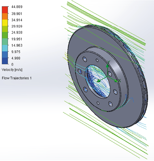
Figure 9a. Behavior of air velocity on the disc 3.
Source: Authors

Figure 9b. Behavior of air velocity on the disc 3, with the behavior of the air flow.
Source: Authors
In Figures 9a and 9b, the air flow reaches a maximum velocity of 44,889 m/s, due to the geometry of the disk and its operating conditions. That for this case is the mayor disk of diameter that therefore reaches greater speed. Therefore, it generates more turbulence within the system. Making the heat dissipation process as fast as possible, helping the effectiveness of the braking process.
Figures 7, 8 and 9 demonstrate the effectiveness of the Brake System in terms of fluid dynamics (Air) circulating through the ventilation channels and in this way rapidly dissipating heat to the environment. In addition, with the help of Sotfware you can have a broader view of the behavior of these systems that are important.
Conclusions
The system that the authors of the research considered to be a reason for study and calculation was the most appropriate, because the elements under consideration are easily accessible and nowadays almost all vehicles have disc brakes ventilated in the four wheels by Their effectiveness in the braking process; Otherwise it occurs in vehicles that continue to use the drum brakes on the rear axle, and usually most of the drawbacks such as the loss of heat, moisture and thus the corrosion that result from the braking inefficiency, because The areas of heat generation are closed and the heat evacuation is delayed.
Taking into account the results obtained, the brake disc 3 dissipates the heat more quickly due to the design of its geometry in its ventilation channels, resulting in a maximum heat loss rate of 44,889 m/s.
For analysis performed in Solidworks software through the Computational Fluid Dynamics (CFD) library to the three brakes to verify the dynamic behavior of the systems in the three disc brakes.
It is of great importance the application of Design Software for Finite Element Analysis (FEA), because it is possible to check, verify and analyze working conditions of the disc brakes, as well as to apply dynamic theory, of which it was evident that these braking systems start from the pedal force.
Acknowledgements
The authors are grateful to the Division of Research and Extension and the Department of Mechanical Engineering of the Universidad Francisco de Paula Santander Ocaña, for their support in the characterization tests of the brake discs, in addition, the financing of scientific events in which show the results of research.
References
Andreaus, U., & Casini, P. (2001). Dynamics of friction oscillators excited by a moving base and/or driving force. Journal of Sound and Vibration,245(4),685–699. http://doi.org/10.1006/jsvi.2000.3555
Bocîi, L. S. (2011).The influence of braking time on heat flow through the friction surfaces of the friction elements of disk brakes for railway vehicles. Transport, 26(1), 75–78. http://doi.org/10.3846/16484142.2011.563494
Cengel, Y. (2007). Tansferencia de calor y masa. Un enfoque práctico. Tercera edición. México: McGraw-Hil.
Chi, Z., He, Y., & Naterer, G. (2009). Convective heat transfer optimization of automotive brake discs. SAE International Journal of Passenger Cars - Mechanical Systems, 2(1), 961–969. http://doi.org/10.4271/2009-01-0859
Dhaubhadel, M. N. (1996). CFD applications in the automotive industry (invited keynote presentation). American Society of Mechanical Engineers, Fluids Engineering Division (Publication) FED, 239, 473–480. Retrieved from https://www.scopus.com/inward/record.uri?eid=2-s2.0-0030351732&partnerID=40&md5=03a0b0206ac6097ab2566376760f4aac
García-León, R. A. (2014). Evaluación del comportamiento de los frenos de disco de los vehículos a partir del análisis de la aceleración del proceso de corrosión. Universidad Francisco de Paula Santander Ocaña. Retrieved from http://repositorio.ufpso.edu.co:8080/dspaceufpso/bitstream/123456789/251/1/25724.pdf
García-León, R. A. (2017). Thermal study in three vented brake discs, using the finite element analysis. DYNA (Colombia), 84(200), 19–27. http://doi.org/https://doi.org/10.15446/dyna.v84n200.55663
García-León, R. A., Acosta Pérez, M. A., & Flórez Solano, E. (2015). Análisis del comportamiento de los frenos de disco de los vehículos a partir de la aceleración del proceso de corrosión. Tecnura, 19(45), 53–63. http://doi.org/10.14483/udistrital.jour.tecnura.2015.3.a04
García-León, R. A., & Flórez Solano, E. (2016). Estudio analítico de la transferencia de calor por convección que afectan los frenos de disco ventilados. Tecnura, 20, 15–30. http://doi.org/10.14483/udistrital.jour.tecnura.2016.SE1.a01
García-León, R. A., & Perez Rojas, E. (2017). Analysis of the amount of heat flow between cooling channels in three vented brake discs. Ingenieria Y Universidad, 21(1), 55–70. http://doi.org/10.11144/Javeriana.iyu21-1.aahf
Gulec, M., Yolacan, E., & Aydin, M. (2016). Design, analysis and real time dynamic torque control of single-rotor-single-stator axial flux eddy current brake. IET Electric Power Applications, 10(9), 869–876. http://doi.org/10.1049/iet-epa.2016.0022
Hirasawa, S., Kawanami, T., & Shirai, K. (2014). Numerical analysis of convection heat transfer on high-temperature rotating disk at bottom surface of air flow duct. In ASME International Mechanical Engineering Congress and Exposition, Proceedings (IMECE) (Vol. 8A). Dept. of Mech. Engineering, Kobe University, 1-1 Rokkodai, Nada-Kobe, Hyogo, Japan. http://doi.org/10.1115/IMECE2014-36142
Izquierdo, F. A. (2011). Teoría de los vehículos automóviles. Segunda Edición (Universida). Madrid, España.
Klimenda, F., Soukup, J., & Kampo, J. (2016). Heat distribution in disc brake. In AIP Conference Proceedings (Vol. 1745). University of J. E. Purkyne in Usti Nad Labem, Faculty of Production Technology and Management, Department of Machines and Mechanics, Pasteurova 3334/7, Usti nad Labem, Czech Republic. http://doi.org/10.1063/1.4953715
Lee, S.-D., & Kim, S.-L. (2010). Characterization and development of the ideal pedal force, pedal travel, and response time in the brake system for the translation of the voice of the customer to engineering specifications. Proceedings of the Institution of Mechanical Engineers, Part D: Journal of Automobile Engineering, 224(11), 1433–1450. http://doi.org/10.1243/09544070JAUTO1585
Meng, D., Zhang, L., & Yu, Z. (2016). A dynamic model for brake pedal feel analysis in passenger cars. Proceedings of the Institution of Mechanical Engineers, Part D: Journal of Automobile Engineering, 230(7), 955–968. http://doi.org/10.1177/0954407015598030
Nagarajan, A., & Narayanan, M. R. (2016). Maximization of efficiency for Disk brake material using composite material by modelling and analysis. International Journal of Control Theory and Applications, 9(6), 2793–2798. Retrieved from https://www.scopus.com/inward/record.uri?eid=2-s2.0-84988599573&partnerID=40&md5=4f98cf86da9aeb8241c83108222522fd
Palmer, E., Mishra, R., & Fieldhouse, J. (2009). An optimization study of a multiple-row pin-vented brake disc to promote brake cooling using computational fluid dynamics. Proceedings of the Institution of Mechanical Engineers, Part D: Journal of Automobile Engineering, 223(7), 865–875. http://doi.org/10.1243/09544070JAUTO1053
Pan, L., Han, J., Li, Z., Yang, Z., & Li, W. (2015). Numerical simulation for train brake disc ventilation. Beijing Jiaotong Daxue Xuebao/Journal of Beijing Jiaotong University, 39(1), 118–124. http://doi.org/10.11860/j.issn.1673-0291-2015.01.020
Pevec, M., Potrc, I., Bombek, G., & Vranesevic, D. (2012). Prediction of the cooling factors of a vehicle brake disc and its influence on the results of a thermal numerical simulation. International Journal of Automotive Technology, 13(5), 725–733. http://doi.org/10.1007/s12239-012-0071-y
Rajagopal, T. K. R., Ramachandran, R., James, M., & Gatlewar, S. C. (2014). Numerical investigation of fluid flow and heat transfer characteristics on the aerodynamics of ventilated disc brake rotor using CFD. Thermal Science, 18(2), 667–675. http://doi.org/10.2298/TSCI111219204R
Riley, W. F., & Sturges, L. D. (1996). Ingeniería Mecánica Dinámica. (Ilusttrada, Ed.) (Reverte). España: Reverte. Retrieved from https://books.google.de/books?id=Vq3HdDHRsz8C
Ruan, J., Walker, P. D., Watterson, P. A., & Zhang, N. (2016). The dynamic performance and economic benefit of a blended braking system in a multi-speed battery electric vehicle. Applied Energy, 183, 1240–1258. http://doi.org/10.1016/j.apenergy.2016.09.057
Shahril, A., Samin, R., Juraidi, J. M., & Daut, J. (2015). Structural analysis of brake disc using dynamic simulation. ARPN Journal of Engineering and Applied Sciences, 10(17), 7805–7808. Retrieved from https://www.scopus.com/inward/record.uri?eid=2-s2.0-84943302748&partnerID=40&md5=86a2f5f660b878a15d1ad45f7c4276d0
Shaw, S. W. (1986). On the dynamic response of a system with dry friction. Journal of Sound and Vibration, 108(2), 305–325. http://doi.org/https://doi.org/10.1016/S0022-460X(86)80058-X
Sobachkin, A., Dumnov, G., & Sobachkin, A. (2014). Base numérica de CFD integrada en CAD. Informe Técnico. SolidWorks.
Surblys, V., & Sokolovskij, E. (2016). Research of the Vehicle Brake Testing Efficiency. In Y. I., B. V., & B. N. (Eds.), 9th International Scientific Conference, Transbaltica 2015 (Vol. 134, pp. 452–458). Vilnius Gediminas Technical University, J. Basanavičiaus g. 28, Vilnius, Lithuania: Elsevier Ltd. http://doi.org/10.1016/j.proeng.2016.01.067
Thuresson, A. (2014). CFD and Design Analysis of Brake Disc. Charlmers University Of Tecnology. Charlmers University Of Tecnology.
Wei, D., Ruan, J., Zhu, W., & Kang, Z. (2016). Properties of stability, bifurcation, and chaos of the tangential motion disk brake. Journal of Sound and Vibration, 375, 353–365. http://doi.org/10.1016/j.jsv.2016.04.022
Wei, W., Hu, Y., Wu, Q., Zhao, X., Zhang, J., & Zhang, Y. (2016). An air brake model for longitudinal train dynamics studies. Vehicle System Dynamics. School of Traffic and Transportation Engineering, Dalian jiaotong University, Dalian, People’s Republic of China: Taylor and Francis Ltd. http://doi.org/10.1080/00423114.2016.1254261
Wu, W., Xiong, Z., Hu, J., & Yuan, S. (2015). Application of CFD to model oil-air flow in a grooved two-disc system. International Journal of Heat and Mass Transfer, 91, 293–301. http://doi.org/10.1016/j.ijheatmasstransfer.2015.07.092
Wurm, J., Fitl, M., Gumpesberger, M., Väisänen, E., & Hochenauer, C. (2016). Novel CFD approach for the thermal analysis of a continuous variable transmission (CVT). Applied Thermal Engineering, 103, 159–168. http://doi.org/10.1016/j.applthermaleng.2016.04.092
Xu, A. Q. (2016). Study on the dynamic characteristics of a high frequency brake based on giant magnetostrictive material. Smart Materials and Structures, 25(6). http://doi.org/10.1088/0964-1726/25/6/065001
Yan, H. B., Feng, S. S., Yang, X. H., & Lu, T. J. (2015). Role of cross-drilled holes in enhanced cooling of ventilated brake discs. Applied Thermal Engineering, 91, 318–333. http://doi.org/10.1016/j.applthermaleng.2015.08.042

Attribution 4.0 International (CC BY 4.0) Share - Adapt
References
Andreaus, U., & Casini, P. (2001). Dynamics of friction oscillators excited by a moving base and/or driving force. Journal of Sound and Vibration, 245(4), 685–699. http:// doi.org/10.1006/jsvi.2000.3555
Bocîi, L. S. (2011). The infl uence of braking time on heat fl ow through the friction surfaces of the friction elements of disk brakes for railway vehicles. Transport, 26(1), 75–78. http://doi.org/10.3846/16484142.2011.563494
Cengel, Y. (2007). Tansferencia de calor y masa. Un enfoque práctico. Tercera edición. México: McGraw-Hill.
Chi, Z., He, Y., & Naterer, G. (2009). Convective heat transfer optimization of automotive brake discs. SAE International Journal of Passenger Cars - Mechanical Systems, 2(1), 961– 969. http://doi.org/10.4271/2009-01-0859
Dhaubhadel, M. N. (1996). CFD applications in the automotive industry (invited keynote presentation). American Society of Mechanical Engineers, Fluids Engineering Division (Publication) FED, 239, 473–480. Retrieved from https://www.scopus.com/inward/record.uri?eid=2-s2.0-
&partnerID=40&md5=03a0b0206ac6097ab 2566376760f4aac
García-León, R. A. (2014). Evaluación del comportamiento de los frenos de disco de los vehículos a partir del análisis de la aceleración del proceso de corrosión. Universidad Francisco de Paula Santander Ocaña. Retrieved from http://repositorio.ufpso.edu.co:8080/dspaceufpso/bitstream/123456789/251/1/25724.pdf
García-León, R. A. (2017). Thermal study in three vented brake discs, using the fi nite element analysis. DYNA (Colombia), 84(200), 19–27. http://doi.org/http://dx.doi.org/10.15446/dyna.v84n200.55663
García-León, R. A., Acosta Pérez, M. A., & Flórez Solano, E. (2015). Análisis del comportamiento de los frenos de disco de los vehículos a partir de la aceleración del proceso de corrosión. Tecnura, 19(45), 53–63. http://doi.org/10.14483/udistrital.jour.tecnura.2015.3.a04
García-León, R. A., & Flórez Solano, E. (2016). Estudio analítico de la transferencia de calor por convección que afectan los frenos de disco ventilados. Tecnura, 20, 15–30. http://doi.org/10.14483/udistrital.jour.tecnura.2016.SE1.a01
García-León, R. A., & Perez Rojas, E. (2017). Analysis of the amount of heat flow between cooling channels in three vented brake discs. Ingenieria Y Universidad, 21(1), 55–70. http://doi.org/10.11144/Javeriana.iyu21-1.aahf
Gulec, M., Yolacan, E., & Aydin, M. (2016). Design, analysis and real time dynamic torque control of single-rotor-singlestator axial flux eddy current brake. IET Electric Power Applications, 10(9), 869–876. http://doi.org/10.1049/ietepa.2016.0022
Hirasawa, S., Kawanami, T., & Shirai, K. (2014). Numerical analysis of convection heat transfer on high-temperature rotating disk at bottom surface of air flow duct. In ASM International Mechanical Engineering Congress and Exposition, Proceedings (IMECE) (Vol. 8A). Dept. of Mech. Engineering, Kobe University, 1-1 Rokkodai, Nada-Kobe, Hyogo, Japan. http://doi.org/10.1115/IMECE2014-36142
Izquierdo, F. A. (2011). Teoría de los vehículos automóviles. Segunda Edición (Universida). Madrid, España.
Klimenda, F., Soukup, J., & Kampo, J. (2016). Heat distribution in disc brake. In AIP Conference Proceedings (Vol. 1745). University of J. E. Purkyne in Usti Nad Labem, Faculty of Production Technology and Management, Department of Machines and Mechanics, Pasteurova 3334/7, Usti nad Labem, Czech Republic. http://doi.org/10.1063/1.4953715
Lee, S.-D., & Kim, S.-L. (2010). Characterization and development of the ideal pedal force, pedal travel, and response time in the brake system for the translation of the voice of the customer to engineering specifications. Proceedings of the Institution of Mechanical Engineers, Part D: Journal of Automobile Engineering, 224(11), 1433– 1450. http://doi.org/10.1243/09544070JAUTO1585
Meng, D., Zhang, L., & Yu, Z. (2016). A dynamic model for brake pedal feel analysis in passenger cars. Proceedings of the Institution of Mechanical Engineers, Part D: Journal of Automobile Engineering, 230(7), 955–968. http://doi.org/10.1177/0954407015598030
Nagarajan, A., & Narayanan, M. R. (2016). Maximization of efficiency for Disk brake material using composite material by modelling and analysis. International Journal of Contro Theory and Applications, 9(6), 2793–2798. Retrieved from https://www.scopus.com/inward/record.uri?eid=2-s2.0-
&partnerID=40&md5=4f98cf86da9aeb8241c83108222522fd
Palmer, E., Mishra, R., & Fieldhouse, J. (2009). An optimization study of a multiple-row pin-vented brake disc to promote brake cooling using computational fluid dynamics. Proceedings of the Institution of Mechanical Engineers, Part D: Journal of Automobile Engineering, 223(7), 865–875. http://doi.org/10.1243/09544070JAUTO1053
Pan, L., Han, J., Li, Z., Yang, Z., & Li, W. (2015). Numerical simulation for train brake disc ventilation. Beijing Jiaotong Daxue Xuebao/Journal of Beijing Jiaotong University, 39(1), 118–124. http://doi.org/10.11860/j.issn.1673-0291-2015.01.020
Pevec, M., Potrc, I., Bombek, G., & Vranesevic, D. (2012). Prediction of the cooling factors of a vehicle brake disc and its influence on the results of a thermal numerical simulation. International Journal of Automotive Technology, 13(5), 725–733. http://doi.org/10.1007/s12239-012-0071-y
Rajagopal, T. K. R., Ramachandran, R., James, M., & Gatlewar, S. C.
(2014). Numerical investigation of fluid flow and heat transfer characteristics on the aerodynamics of ventilated disc brake rotor using CFD. Thermal Science, 18(2), 667– 675. http://doi.org/10.2298/TSCI111219204R
Riley, W. F., & Sturges, L. D. (1996). Ingeniería Mecánica Dinámica.
(Ilusttrada, Ed.) (Reverte). España: Reverte. Retrieved from https://books.google.de/books?id=Vq3HdDHRsz8C
Ruan, J., Walker, P. D., Watterson, P. A., & Zhang, N. (2016). The dynamic performance and economic benefit of a blended braking system in a multi-speed battery electric vehicle. Applied Energy, 183, 1240–1258. http://doi.org/10.1016/j.apenergy.2016.09.057
Shahril, A., Samin, R., Juraidi, J. M., & Daut, J. (2015). Structural analysis of brake disc using dynamic simulation. ARPN Journal of Engineering and Applied Sciences, 10(17), 7805–7808. Retrieved from https://www.scopus.com/inward/record.uri?eid=2-s2.0-84943302748&partnerID=40&md5=86a2f5f660b878a15d1ad45f7c4276d0
Shaw, S. W. (1986). On the dynamic response of a system with dry friction. Journal of Sound and Vibration, 108(2), 305–325. http://doi.org/http://dx.doi.org/10.1016/S0022-460X(86)80058-X
Sobachkin, A., Dumnov, G., & Sobachkin, A. (2014). Base numérica de CFD integrada en CAD. Informe Técnico. SolidWorks.
Surblys, V., & Sokolovskij, E. (2016). Research of the Vehicle Brake Testing Efficiency. In Y. I., B. V., & B. N. (Eds.), 9th International Scientific Conference, Transbaltica 2015 (Vol. 134, pp. 452–458). Vilnius Gediminas Technical University, J. Basanavičiaus g. 28, Vilnius, Lithuania: Elsevier Ltd. http://doi.org/10.1016/j.proeng.2016.01.067
Thuresson, A. (2014). CFD and Design Analysis of Brake Disc. Charlmers University Of Tecnology. Charlmers University Of Tecnology.
Wei, D., Ruan, J., Zhu, W., & Kang, Z. (2016). Properties of stability, bifurcation, and chaos of the tangential motion disk brake. Journal of Sound and Vibration, 375, 353–365. http://doi.org/10.1016/j.jsv.2016.04.022
Wei, W., Hu, Y., Wu, Q., Zhao, X., Zhang, J., & Zhang, Y. (2016). An air brake model for longitudinal train dynamics studies. Vehicle System Dynamics. School of Traffic and Transportation Engineering, Dalian jiaotong University, Dalian, People’s Republic of China: Taylor and Francis Ltd. http://doi.org/10.1080/00423114.2016.1254261
Wu, W., Xiong, Z., Hu, J., & Yuan, S. (2015). Application of CFD to model oil-air flow in a grooved two-disc system. International Journal of Heat and Mass Transfer, 91, 293–301. http://doi.org/10.1016/j.ijheatmasstransfer.2015.07.092
Wurm, J., Fitl, M., Gumpesberger, M., Väisänen, E., & Hochenauer, C.
(2016). Novel CFD approach for the thermal analysis of a continuous variable transmission (CVT). Applied Thermal Engineering, 103, 159 168. http://doi.org/10.1016/j.applthermaleng.2016.04.092
Xu, A. Q. (2016). Study on the dynamic characteristics of a high frequency brake based on giant magnetostrictive material. Smart Materials and Structures, 25(6). http://doi.org/10.1088/0964-1726/25/6/065001
Yan, H. B., Feng, S. S., Yang, X. H., & Lu, T. J. (2015). Role of cross drilled holes in enhanced cooling of ventilated brake discs. Applied Thermal Engineering, 91, 318–333. http://doi.org/10.1016/j.applthermaleng.2015.08.042
How to Cite
APA
ACM
ACS
ABNT
Chicago
Harvard
IEEE
MLA
Turabian
Vancouver
Download Citation
CrossRef Cited-by
1. Anil Babu Seelam, Nabil Ahmed Zakir Hussain, Sachidananda Hassan Krishanmurthy. (2021). Design and analysis of disc brake system in high speed vehicles. International Journal for Simulation and Multidisciplinary Design Optimization, 12, p.19. https://doi.org/10.1051/smdo/2021019.
2. R. A. García-León, D. Páez-Gómez, G. Guerrero-Gómez. (2023). Theoretical design of a brake discs tribological machine. International Journal of System Assurance Engineering and Management, 14(4), p.1530. https://doi.org/10.1007/s13198-023-01962-9.
3. R. A. García-León, N. Afanador-García, J. A. Gómez-Camperos. (2021). Numerical Study of Heat Transfer and Speed Air Flow on Performance of an Auto-Ventilated Disc Brake. Fluids, 6(4), p.160. https://doi.org/10.3390/fluids6040160.
4. Ricardo Andrés García-León, Jhon Herrera-Perea, Jorge Cerón-Guerrero. (2020). Improvement of the mechanical properties of nodular gray cast iron with the application of heat treatments. Revista Ingenio, 17(1), p.21. https://doi.org/10.22463/2011642X.2653.
5. Kejela Temesgen Deressa, Demiss Alemu Ambie. (2022). Thermal Load Simulations in Railway Disc Brake: A Systematic Review of Modelling Temperature, Stress and Fatigue. Archives of Computational Methods in Engineering, 29(4), p.2271. https://doi.org/10.1007/s11831-021-09662-y.
6. R A García-León, A Bohorquez-Niño, J F Barbosa-Paredes. (2019). Design of an extrusion machine for the manufacture of plastic tubes. Journal of Physics: Conference Series, 1257(1), p.012006. https://doi.org/10.1088/1742-6596/1257/1/012006.
7. R A García-León, E Flórez-Solano, M Rodriguez-Castilla. (2019). Thermo-mechanical assessment in three auto-ventilated disc brake by implementing finite elements. Journal of Physics: Conference Series, 1257(1), p.012019. https://doi.org/10.1088/1742-6596/1257/1/012019.
8. Ricardo Andres García-León, Wilder Quintero-Quintero, Magda Rodriguez-Castilla. (2019). Thermal analysis of three motorcycle disc brakes. Smart and Sustainable Built Environment, 9(2), p.208. https://doi.org/10.1108/SASBE-07-2019-0098.
9. R. A. García-León, G. Guerrero-Gómez, N. Afanador-García. (2023). Experimental analysis of the heat transfer generated during the operation of an automotive disc brake. Australian Journal of Mechanical Engineering, 21(4), p.1247. https://doi.org/10.1080/14484846.2021.1974660.
10. Piotr Grzes, Michal Kuciej, Piotr Wasilewski. (2025). Numerical modeling of heat generation process in a disk brake at three thermal contact conditions over an extended braking distance. Numerical Heat Transfer, Part A: Applications, 86(19), p.6808. https://doi.org/10.1080/10407782.2024.2345860.
11. R A García-León, W Quintero-Quintero, J A Gomez-Camperos. (2020). Mathematical analysis of the dynamic behavior three motorcycle disc brakes. Journal of Physics: Conference Series, 1708(1), p.012025. https://doi.org/10.1088/1742-6596/1708/1/012025.
12. Jorge Antonio Velasco Parra, Bladimir A. Ramón Valencia, William Javier Mora Espinosa. (2020). Composite materials reinforced with ceramic waste and matrix of unsaturated polyester for applications in the automotive industry. DYNA, 87(212), p.251. https://doi.org/10.15446/dyna.v87n212.81483.
Dimensions
PlumX
Article abstract page views
Downloads


License
Copyright (c) 2017 Ricardo A. García-León, Eder Flórez-Solano

This work is licensed under a Creative Commons Attribution 4.0 International License.
The authors or holders of the copyright for each article hereby confer exclusive, limited and free authorization on the Universidad Nacional de Colombia's journal Ingeniería e Investigación concerning the aforementioned article which, once it has been evaluated and approved, will be submitted for publication, in line with the following items:
1. The version which has been corrected according to the evaluators' suggestions will be remitted and it will be made clear whether the aforementioned article is an unedited document regarding which the rights to be authorized are held and total responsibility will be assumed by the authors for the content of the work being submitted to Ingeniería e Investigación, the Universidad Nacional de Colombia and third-parties;
2. The authorization conferred on the journal will come into force from the date on which it is included in the respective volume and issue of Ingeniería e Investigación in the Open Journal Systems and on the journal's main page (https://revistas.unal.edu.co/index.php/ingeinv), as well as in different databases and indices in which the publication is indexed;
3. The authors authorize the Universidad Nacional de Colombia's journal Ingeniería e Investigación to publish the document in whatever required format (printed, digital, electronic or whatsoever known or yet to be discovered form) and authorize Ingeniería e Investigación to include the work in any indices and/or search engines deemed necessary for promoting its diffusion;
4. The authors accept that such authorization is given free of charge and they, therefore, waive any right to receive remuneration from the publication, distribution, public communication and any use whatsoever referred to in the terms of this authorization.