Published
Numerical Assessment of Bidirectional Roller Bearing Isolators under Near-Fault Earthquakes
Evaluación numérica de aisladores de soportes rodantes bidireccionales sometidos a sismos cercanos a la falla
DOI:
https://doi.org/10.15446/ing.investig.104078Keywords:
base isolation, nonlinear seismic response, supplementary dissipation mechanism, inclination angle (en)aislamiento de base, respuesta sísmica no lineal, mecanismo de disipación suplementario, ángulo de inclinación (es)
In this research, a bidirectional seismic isolation device composed of sloped bearing plates and multiple rollers arranged in both orthogonal-in-plane directions is numerically studied. A previous analytical model of a single direction of roller bearing (RB) system is extended to a two-direction RB system. Several experimental tests in a physical building model with and without an RB system are used to validate the numerical model. The model is used to perform the nonlinear response of a four-story multi-column building when subjected to pairs of scaled near-fault earthquake records. The effect of the inclination angle of bearing plates in the range of 1.0° to 4.0°, the sliding friction force, and supplementary damping mechanisms ranging from 0.0 to 0.5 N/kg (i.e. friction force normalized with the structure mass) are also investigated. The results show that the proposed bidirectional RB system is suitable for reducing the seismic response of stiff and flexible multi-column structures. In particular, the RB system reduces the acceleration responses by 5% to 85% in flexible structures and 86% to 96% in stiff structures. Furthermore, bearing plates with an inclination angle greater than or equal to 3.0° have significant benefits in terms of self-centering capacity.
En este trabajo de investigación se estudia la efectividad de un sistema de aislamiento sísmico bidireccional compuesto por superficies de rodamiento inclinadas y múltiples rodillos dispuestos en ambas direcciones ortogonales en el plano. Resultados experimentales anteriores de aisladores sísmicos de soportes rodantes unidireccionales y bidireccionales (RB), fueron utilizados para validar un modelo numérico 3D de edificios con RB. Este modelo de comportamiento no lineal se utilizó para obtener la respuesta de un edificio de cuatro pisos sometido a pares de registros escalados de terremotos cercanos a la falla. Este estudio, investiga el efecto del ángulo de inclinación de las superficies rodantes en el rango de 1.0° a 4.0°, la fuerza de fricción por rodamiento y los mecanismos de disipación de energía por deslizamiento, tomando una variación entre 0.0 a 0.5 N/kg en la magnitud de la fuerza de fricción normalizada respecto a la masa de la estructura. Los resultados muestran que el sistema RB propuesto es adecuado para reducir la respuesta sísmica de edificios con comportamiento rígido y flexible. En particular, el sistema RB reduce las respuestas de aceleración entre un 5 % y un 85 % en estructuras flexibles y entre un 86 % y un 96 % en estructuras rígidas. Además, las superficies con un ángulo de inclinación mayor o igual a 3,0° muestran ventajas significativas en relación a la capacidad de auto centrado.
Recibido: 3 de agosto de 2022; Aceptado: 27 de septiembre de 2023
ABSTRACT
Base isolation with roller bearing systems has been widely studied in recent years due to its successful performance in the seismic protection of buildings and bridges. This paper numerically evaluates the effectiveness of a bi‑directional roller bearing (RB) seismic isolation system composed of sloped bearing plates and multiple rollers arranged in both orthogonal‑in‑plane directions. Previous experimental results obtained with unidirectional and bidirectional RBs were used to validate the 3D numerical model of an isolated building with RBs. The model was used to obtain the nonlinear response of a four‑story multi‑column building when subjected to pairs of scaled near‑fault earthquake records. The effects of the bearing plate inclination angle (ranging from 1.0 to 4.0°), the sliding friction force, and supplementary dissipation mechanisms (0.0‑0.5 N/kg, i.e. friction force normalized with the structure mass) were evaluated. The results show that the proposed bidirectional RB system is suitable for reducing the seismic response of stiff and flexible multi‑column structures. In particular, the RB system reduces the acceleration responses by 5‑85% in flexible structures and by 86‑96% in stiff ones. Furthermore, bearing plates with an inclination angle greater than or equal to 3.0° have significant benefits in terms of self‑centering capacity.
Keywords
base isolation, nonlinear seismic response, supplementary dissipation mechanism, inclination angle.RESUMEN
El aislamiento de base con sistemas de rodamiento ha sido ampliamente estudiado en los últimos años debido a su exitoso desempeño en la protección sísmica de puentes y edificaciones. Este artículo evaluó numéricamente la efectividad de un sistema de aislamiento sísmico bidireccional de soportes rodantes (RBs) compuesto por superficies de rodamiento inclinadas y múltiples rodillos dispuestos en ambas direcciones ortogonales en el plano. Se utilizaron resultados obtenidos con RBs unidireccionales y bidireccionales para validar el modelo numérico 3D de un edificio aislado con RBs. Se utilizó el modelo para obtener la respuesta no lineal de un edificio multicolumna de cuatro pisos frente a pares de registros escalados de terremotos cercanos a la falla. Se evaluaron los efectos del ángulo de inclinación de la superficie de rodamiento (en el rango de 1.0 a 4.0°), de la fuerza de fricción por rodamiento y de mecanismos suplementarios de disipación (0.0‑0.5 N/kg, i.e., fuerza de fricción normalizada con la masa de la estructura). Los resultados muestran que el sistema de RBs bidireccionales propuesto es adecuado para reducir la respuesta sísmica de estructuras multicolumna rígidas y flexibles. En particular, el sistema de RBs reduce las respuestas de aceleración en 5‑85 % en estructuras flexibles y en 86‑96 % en estructuras rígidas. Además, las superficies de rodamiento con un ángulo de inclinación mayor o igual a 3.0° muestran beneficios significativos respecto a su capacidad de autocentrado.
Palabras clave
aislamiento de base, respuesta sísmica no lineal, mecanismo de disipación suplementario, ángulo de inclinación.Introduction
Isolation systems have been successfully used since 1969 in 12 720 projects worldwide (Walters, 2015). Although the earliest applications of these seismic protection mechanisms were related to critical buildings such as hospitals and emergency facilities, they have recently been extended to ensure a better seismic response in lower and mid-rise residential building projects (Wang et al., 2017).
This technology has been implemented in new construction projects, updating structures to current standards, and in the retrofitting of structures with insufficient earthquake (EQ) resistance (Naeim and Kelly, 1999); (Tsai, Wu, Chang, and Lee, 2007); (Matsagar and Jangid, 2008); (Hosseini and Soroor, 2011), (2013); (Erdik, Ulker, Sadan, and Tuzun, 2018); (Ryan, Okazaki, Coria, Sato, and Sasaki, 2018). Nevertheless, the widespread application of these devices is a current challenge that requires improving existing methods and developing cost-effective alternative devices and other isolation strategies (Bagerzadeh‑Karimi and Genes, 2019); (Calhoun, Tehrani, and Harvey‑Jr, 2019); (Beirami‑Shahabi, Zamani‑Ahari, and Barghian, 2020); (Zhang and Ali, 2021).
Seismic isolation systems are the most commonly used devices in earthquake‑resistant structures. Natural rubber bearings (NRB), lead rubber bearings (LRB), high‑damping rubber bearings (HDRB), slider bearings, and mono‑, double‑, and triple‑friction pendulum (FP) systems stand out for their design simplicity and effectiveness. Some isolated structure projects and the development of new materials were described by (De Luca and Guidi, 2019) and (Nobari Azar, Karimzadeh Naghshineh, and Sen, 2022). An isolation seismic layer must provide (i) low lateral stiffness, (ii) re‑centering capacity, and (iii) supplementary damping. Recently, roller seismic isolation bearings (RSIB) have gained attention, as (Lee, Liang, and Snyder, 2005) reported and showcased the advantages of their patent (WO 2005/031088 A2).
Several studies have shown that roller bearing (RB) isolators exhibit excessive displacements under near‑fault ground records (Rawat, Ummer, and Matsagar, 2018), in addition to stress concentration and lower friction resistance (Beirami‑Shahabi et al., 2020). Moreover, an elementary RB isolator device does not offer integrated displacement control (Zhang and Ali, 2021). These issues can be mitigated via energy dissipation devices (Ortiz‑Cano, Magluta, and Roitman, 2015), e.g., by implementing shock absorbers with a particular bumper and gap configuration (Andreaus and De Angelis, 2020) or by introducing traditional springs (Zhang and Ali, 2021).
Numerous attempts have been made to implement RB devices with a low friction force in order to cover a wide range of earthquake intensities, but they have resulted in unnecessarily high isolator displacements (Rawat et al., 2018); (Rawat and Matsagar, 2021). Period‑matching effects (tuned to the natural period of the building) may arise in RB systems, even when located on lower floors (Harvey‑Jr and Gavin, 2015). Furthermore, ground motions with long‑period components that reach the natural period of the isolator device may weaken its performance (Calhoun, 2018); (P. Chen, Hsu, Zhong, and Wang, 2021). In this sense, the robustness of RB isolators could be enhanced through a tailored design based on seismic demand characteristics, such as ground motion period and intensity (Harvey‑Jr and Gavin, 2015).
Sliding friction mechanisms are commonly integrated into RB systems to provide additional friction force while reducing the peak displacement (Lee, Ou, Niu, Song, and Liang, 2010). However, friction is deteriorated over time due to wear during recurrent loading cycles and weathering from external conditions (Lee et al., 2010), in addition to the sliding velocity, surface temperature, and other physical phenomena (Lee et al., 2010); (Zhang and Ali, 2021). (Foti, Catalan Goni, and Vacca, 2013) proposed an alternative dissipation mechanism: a two‑layer rubber cover attached to the lower and upper plates of RB devices, i.e., a rubber‑layer roller bearing (RLRB) isolation device for low‑rise lightweight structures and equipment applications. This mechanism provides a higher damping capacity than typical steel‑steel friction devices. However, given the potential resonance during seismic events with a predominance of low frequencies and the computational effort required to solve the contact problem, this type of mechanism has not been implemented in all building systems (Foti, 2019). In this vein, there is a research opportunity to develop reliable analytical and numerical models aimed at predicting the behavior of isolation systems (Beirami‑Shahabi et al., 2020).
This paper aims to study a bidirectional seismic isolation device composed of multiple rollers in the direction of the orthogonal plane. First, the model developed by (Ortiz‑Cano et al., 2015) is extended to couple the bidirectional nonlinear responses of the RB system when subjected to a pair of horizontal ground motion components. The numerical model is validated via several tests with a scaled building model, the RB system, and a combination of both. Then, the performance of low‑rise and mid‑rise buildings with the RB system is numerically evaluated against near‑fault ground motions for several bearing plate slope angles and sliding friction forces. In the final section, some remarks and recommendations are provided.
Dynamic behavior of isolated buildings with RB systems
(Ortiz‑Cano et al., 2015) studied a sloped roller‑type isolation device in which multiple rollers move between a V‑shaped bearing plate and a flat surface in a single horizontal direction. This formulation was augmented to include two ground motion components. The dynamic behavior of isolated buildings with RBs under base excitations in a system with multiple degrees of freedom (MDoF) can be represented in the time domain via Equation (1).
(1) M\ddot{u} + C\dot{u} + Ku + R(f_s + f_{dr} + f_{ds}) = -M\Gamma \ddot{u}_gwhere M, C, and K are the mass, damping, and stiffness matrices of the MDoF system, respectively. In addition, \ddot{u}, \dot{u}, and u are the acceleration, velocity, and displacement vectors; R is a matrix that allocates the forces of restoration (fs), rolling friction (fdr), and sliding friction (fds) of the RB system in the j direction, into a matrix containing the forces of the MDoF system in the i direction. The elements that make up the R vector take values of 0 or 1 as follows: Rij = 1 if, in DoF i, the forces fs, fdr, and fds are in the j direction; otherwise, Rij = 0.
The forces fs, fdr, and fds, which characterize the RB system along one horizontal motion path, were extended for two orthogonal directions. These forces are defined in tensor notation through Equations (2), (3), and (4).
(2) f_s^{\mathrm{T}} = \{\frac{1}{2}m_1 g \sin(\theta_1) f_{H_1}(u) \quad \frac{1}{2}m_2 g \sin(\theta_2) f_{H_2}(u)\} (3) f_{dr}^{\mathrm{T}} = \{\mu_{r_1} m_1 g f_{H_1}(\dot{u}) \quad \mu_{r_2} m_2 g f_{H_2}(\dot{u})\} (4) f_{ds}^{\mathrm{T}} = \{\mu_{s_1} N_1 f_{H_1}(\dot{u}) \quad \mu_{s_2} N_2 f_{H_2}(\dot{u})\}where m is the mass supported by the bearing plates of the RB system; g is the gravitational acceleration; µr is the rolling friction coefficient; µs is the sliding friction coefficient; N is the normal force on the sliding interface; and θ is the angle of the V‑shaped surfaces. The subscripts 1 and 2 denote the direction of each quantity in the horizontal plane.
fH is a suitable function that replaces the sign function used in earlier models of RB systems, and it allows to simulate a smoother transition between the V‑shaped surfaces. In this work, the function proposed by (Ortiz‑Cano, Magluta, and Roitman, 2014); (Ortiz‑Cano et al., 2015) was used. The Ortiz‑Cano function was written in terms of a parameter called yield displacement d and an auxiliary variable x associated with the displacement and speed of the system's base. This function is defined by
(5) f_H(x) = \begin{cases} 1 & \text{if } x \ge d \\ \frac{1}{d} x & \text{if } -d < x < d \\ -1 & \text{if } x \le -d \end{cases}Finally, in Equation (1), \ddot{u}_g is the seismic excitation vector containing the base accelerations for each direction in which the building can be excited, i.e., three translational and three rotational DoF in the Cartesian space. The term Γ is an influence matrix that relates the excited DoF i with the direction of the seismic excitation j. The elements of the Γ matrix take values of 0 or 1 according to the following rule:
(6) \Gamma_{ij} = \begin{cases} 0 & \text{if DoF } i \text{ is not excited in the } j \text{ direction} \\ 1 & \text{if DoF } i \text{ is excited in the } j \text{ direction} \end{cases}To solve Equation (1), the ode23t numerical solver of ordinary differential equations (ODE) of MATLAB (The MathWorks Inc., 2019) was used, given its great efficiency and numerical stability when compared to other methods in the MATLAB's ODE pack. In general terms, the algorithm of this solver is an implementation of the trapezoidal rule with an adaptive step size associated with the use of a free interpolant (Shampine, Reichelt, and Kierzenka, 1999). The use of this solver requires that Equation (1), a second order equation, be rewritten as a first‑order ODE system, as shown in the following expression:
(7) \dot{v} = A_1 v(t) + A_2 H(u,\dot{u}) + A_3 \ddot{u}_gwith
(8) A_1 = \begin{bmatrix} 0 & I \\ -M^{-1}K & -M^{-1}C \end{bmatrix} (9) A_2 = \begin{bmatrix} 0 & 0 \\ -M^{-1}R & \end{bmatrix} (10) A_3 = \begin{bmatrix} 0 & 0 \\ -\Gamma & \end{bmatrix}where, A1 and v(t)T = {u \dot{u}} denote the matrix of properties and the response vector of the system in a state‑space form. The non‑linearity of the system is represented by the H(u, u̇) function, which includes the effects of the RB system.
Model validation
The results of an experimental evaluation and the numerical simulation of a building with and without RB isolation were compared in order to validate the numerical model. This section describes the characteristics of the building and the numerical model under study.
Building
The physical model of the frame building corresponds to the one studied by (Ortiz‑Cano et al., 2014), (2015). It consists of a four‑story‑one‑bay frame structure supported by polymeric columns with a rectangular cross‑section of 20.0 \times 2.9 \text{ mm}. The model has a total height of 803.4 \text{ mm} and a floor area of 150 \times 200 \text{ mm}. The slabs and the story‑column joints are constructed from aluminum plates. The base of the building has a thickness of 8.0 \text{ mm}, and the stories and story‑column joints have a thickness of 4.0 \text{ mm}. In addition, the building has lumped additional masses of 0.50 \text{ kg} on the second and third stories. A detailed outline of the experimental model's geometry is shown in Figure 1.
Figure 1.: Physical model geometry. Measures in mm.
According to the modal identification tests (i.e., impulsive excitation on the first floor with a hammer) carried out by (Ortiz‑Cano et al., 2014), (2015) and the analysis of floor acceleration time series using the short‑time Fourier transform (STFT) method, the modal parameters (mean values and standard deviations) identified for the fixed‑base building model are summarized in Table 1.
Table 1.: Identified dynamic properties of the building
In addition, Rayleigh damping constant values of \alpha = 4.03 \cdot 10^{-1} and \beta = 5.58 \cdot 10^{-5} were determined for the first two modes of vibration (which add up to a 95% modal participation of the total mass of the building), as the Rayleigh damping model was used to assemble the damping matrix C within the numerical simulation algorithm.
RB system
We studied the seismic behavior of a bidirectional RB isolation system composed mainly of two surfaces and an array of rollers in an orthogonal arrangement. Previous works have shown that the use of these isolation systems enhances the dynamic response of structures subjected to seismic excitations (Ortiz‑Cano et al., 2014); (Menga, Foti, and Carbone, 2017). However, this isolation scheme has some drawbacks involving the self‑centering mechanism and roller bearing support stability (Sanchez‑Torres, Rico‑Caviedes, Ortiz‑Cano, Nieto‑Leal, and Gaviria‑Mendoza, 2019).
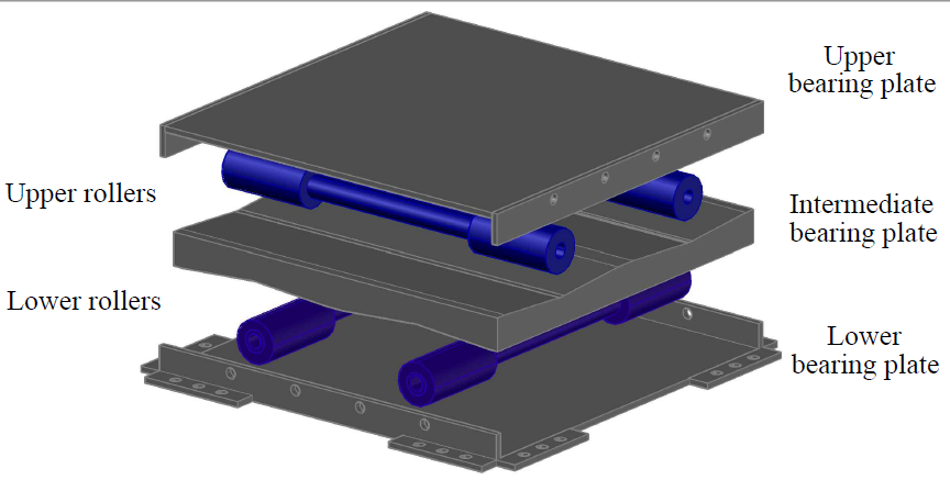
Therefore, the bidirectional isolation system includes an intermediate V‑shaped bearing plate inclined in both directions, as seen in Figure 2, which allows both attenuating the building's acceleration response and ensuring its return to the initial position (self‑centering capacity) after a ground motion event. To avoid pounding between the rollers and the V‑shaped intersection, a rolling arc zone with a fixed curvature radius higher than the roller radius is used, aiming to maintain a predominantly linear sloping surface (Wang et al., 2014). In addition, energy dissipation occurs through lateral frictional plates.
Figure 2.: Bidirectional RB model
Numerical model
3D frame elements were considered, which are characterized by the elasticity modulus E, the Poisson ratio ν that defines the shear modulus G, the density ρ, the area A, the polar moment of inertia Jx, and the moments of inertia Iy and Iz. The axis of the 3D frame elements in local coordinates coincides with the x direction in global coordinates according to the adopted coordinate system, which is implicitly shown in Figure 3. In the numerical representation of the physical model, three types of 3D frame elements were used. Table 2 lists their characteristics.
Table 2.: Mechanical and geometric characteristics of the elements
Figure 3.: Model components
Element type 1 represents the columns constructed in a polymeric material, while types 2 and 3 correspond to the aluminum connections and the slabs defined as beams in the numerical model (Figure 3). It is noteworthy that the density of component 3 takes the value of 0 kg/m3 because the slab masses, as well as other factors that provide weight on each story, were modeled as masses concentrated at the nodes of each floor. Thus, concentrated masses of 539.3, 196.6, 321.2, 321.1, and 196.6 g were incorporated for the nodes of the base and the first, second, third, and fourth floors.
The area and the inertia values were established by geometric definition. For type 2 and 3 elements, the typical E and ν values for aluminum reported in the literature were assumed. For type 1 elements, an average ν value that is typical of polymeric materials was assumed, and E was tuned from the value used by (Ortiz‑Cano, 2013) to obtain the best representation of the structure under fixed‑base conditions.
Model assessment
A comparative analysis of the numerical and experimental responses of the building, the RB system, and the building with the RB system is presented below.
The simulated building response was validated in the frequency and time domains for the fixed‑base building model. To this effect, the frequency response functions (FRFs) and the accelerations of the floors were used.
Figure 4 shows that the natural frequencies, which were numerically obtained, correspond to experimental measures with a maximum difference of 0.4%. In general, the energy (FRF amplitude) follows the pattern of the experimental results for all the modes and natural frequencies of the numerical model. Thus, the fixed‑base building model was evaluated in the frequency domain.
Figure 4.: FRFs comparison for the third floor
The acceleration response of the proposed numerical model and the experimental measures under white noise base excitation are depicted in Figure 5. It can be observed that the acceleration estimated via the numerical simulation agrees with the experimental response regardless of the acceleration level reached.
Figure 5.: Time series of the acceleration response of the third floor under base excitation
In the RB system, the damping provided by the friction between the roller and the sloping surfaces was estimated from the experimental acceleration response of the RB system under free vibration. To this effect, an initial displacement for both horizontal directions was applied. In the numerical model, the roller friction parameter µr was tuned using an iterative manual scheme to match the RB response in both directions. A value of µr = 0.0057 was found to be suitable for each motion direction. To validate the dynamical behavior of the bidirectional RB isolation system, masses of 1.90 and 2.78 kg were considered for the intermediate floors and the base plate, respectively. These values correspond to the physical properties of this structure.
Figure 6 compares the free vibration response of the physical and numerical models. It can be observed that the numerical representation follows the same pattern recorded in the experimental test in both directions.
Figure 6.: Time series of the acceleration response of the RBs under free vibration
A time lag between the numerical and experimental acceleration is observed when the RBs are close to the equilibrium position, i.e., the vertex of V‑shape surfaces. This limitation in the model fit is associated with surface imperfections in the vertex, which increase friction and compromise the performance of the isolator. The repetitive path of numerically simulated response advanced the experimental acceleration record after 6.5 s, indicating that the damping of the RB device is reduced with time (Figure 6a). Furthermore, in the orthogonal direction, the response in the y‑direction (Figure 6b) shows that the square form of the numerical acceleration has a time delay with the experimental acceleration after 4.0 s, indicating that the damping of the RB device increases as the displacement of the RBs decreases. Although the model does not capture the experimental measurements with absolute accuracy, particularly when the system is close to stopping, it can correctly represent the overall behavior of the system.
The acceleration response of the building coupled with the RB system was analyzed under free vibration and subjected to white noise excitation, as shown in Figure 7. It can be seen that the simulated response of the numerical model follows the trend of the target values (labeled as experimental in Figure 7) for this kind of dynamic load, which is particularly important for providing a reliable analysis in the following sections.
Figure 7.: Time series of the acceleration response of the second floor
RB system performance against near‑fault earthquakes
This section evaluates the performance of the RB system in reducing the structural response of buildings when subjected to the horizontal components of two near‑fault seismic records.
The two structures considered are the product of a partial modification to the validated numerical model, which aimed to obtain (i) an S1 model in which the vibration frequencies of the first two modes were less than 2.0 Hz and (ii) an S2 model in which the vibration frequencies of the first two modes were greater than 10.0 Hz, representing buildings with low and high lateral stiffness, respectively.
This modification was made by affecting the inertias Iy and Iz of type 1 components (i.e., columns). For the S1 model, Iy was reduced to 3.0 \cdot 10^{-12} \text{ m}^4, and Iz to 2.0 \cdot 10^{-12} \text{ m}^4. Moreover, for the S2 model, Iy was reduced to 1.0 \cdot 10^{-10} \text{ m}^4, and Iz was increased to 1.0 \cdot 10^{-10} \text{ m}^4. Table 3 shows the predominant frequencies of the modified structures corresponding to the first three modes of vibration.
Table 3.: Vibration modes and frequencies of models S1 and S2
Near‑fault earthquakes are generally characterized by long‑duration, large‑magnitude displacement pulse with large accelerations and a limited frequencies band compared to far‑fault earthquakes. This form of seismic pulse (Mukhopadhyay and Gupta, 2013) creates a significant isolator displacement demand (Rawat et al., 2018). Considering the above, we used near‑fault seismic records obtained from PEER Ground Motion Database (Ancheta et al., 2014), as shown in Table 4 were used. It should be noted that these records have been widely employed in the literature (Ou, Song, and Lee, 2010); (Ortiz‑Cano et al., 2015); (Rawat et al., 2018), since they provide appreciably large ground displacement quantities induced by the hanging wall effect (Donahue and Abrahamson, 2014) and or the fling‑step effect (X. Chen, Liu, Zhou, and Yang, 2020). Vertical ground motions components were not used because they have a negligible effect on the performance of different isolation devices (Ou et al., 2010); (Beirami‑Shahabi, Zamani‑Ahari, and Barghian, 2019).
Table 4.: Near‑fault earthquake records
Since the S1 and S2 models were derived from a physical model, the displacement amplitude of the selected seismic records was scaled to 5% of their PGD. The ground motions were scaled using the Make Quake program software (Quanser Consulting Inc., 2010), which implements the scaling algorithm developed by (Kausel and Ushijima, 1979), allowing to preserve both the acceleration magnitude and the frequency content of the original seismic signal. This procedure incorporates a parabolic baseline correction over different integration schemes in the frequency domain, i.e., the continuous (aliasing), pseudo‑continuous, central difference, and linear acceleration schemes, obtaining consistent results between the time domain and the frequency domain.
First, the performance of the S1 and S2 models when subjected to excitations under fixed base conditions was studied. Then, the RB system was added, considering four slope angles in both directions of the V‑shaped surfaces: 1.0, 2.0, 3.0, and 4.0°. The selected performance parameters were the root mean square (RMS) of the top floor's absolute acceleration of the structure (\ddot{u}_{n=N}, where N is the top floor) and the relative displacement of the isolator (u_b = u_{n=0} - u_g, where ug is the induced displacement of the ground motion).
The absolute accelerations and base displacements provide a proportion of the lateral forces induced by the seismic excitation and the critical design point of the isolator devices, respectively (Jangig, 2000); (Rawat et al., 2018). Figures 8 and 9 present the acceleration response of the fourth floor in both orthogonal directions and the hysteresis diagram of the RB system for each structure when subjected to the most challenging ground motions.
Figure 8.: Response of model S1 when subjected to the scaled earthquake record of Northridge (1994) Newhall - FS
Figure 9.: Response of model S2 when subjected to the scaled earthquake record of Imperial Valley (1979) El Centro - Array #5
Figures 8 and 9 show that all configurations reduce the structural response of models S1 and S2. The acceleration at the top floor is reduced as its slope angle decreases, achieving a peak acceleration reduction of 80‑95% in the lowest slope angle configuration. As expected, the inclination of the plate induces additional forces (restoration forces) that increase the horizontal acceleration of the structure. However, the application of the V‑shape surface includes an energy dissipation system, where re‑centering capabilities are required to avoid residual displacements, as described below.
Figure 8b shows that, even though the peak acceleration is reduced by the RB system in all cases, the maximum amplitude of the isolated structure's response to the excitation is close to that of the structure with the fixed base for a 3.0° inclination angle. To evaluate the changes in the total duration of the building's response records, the RMS was used as a suitable response variation indicator. Thus, the performance of the RB system in terms of the RMS was analyzed for each of the simulations carried out. To this effect, we determined the control effectiveness (CE) of the response of the building with the RB system on a particular story as follows:
(11) CE[\%] = \frac{\sigma_u - \sigma_c}{\sigma_u} \cdot 100where σc and σu denote the directional combination of the RMS values corresponding to both orthogonal directions of the building's motions (i.e., σx and σz) with and without the RB system. Thereby, σc and σu were calculated for each story of the structure by means of the square root of the sum of the squares (SRSS) of the RMS values in the x and z directions (i.e., \sqrt{\sigma_x^2 + \sigma_z^2}).
Figures 10 and 11 summarize the CE of the response of the building with the RB system for different rolling surface slope angles per floor.
Figure 10.: Contour plot of acceleration CE vs. V‑shape surface angle for the S1 structure
Figure 11.: Contour plot of acceleration CE vs. V‑shape surface angle for the S2 structure
In the S1 model with the RB system, the response of the building can reach reductions of 5‑85% (Figure 10). The accelerations at the top floor decreases with the slope angle, achieving reductions of 80‑95% in peak acceleration with the lowest slope angle configuration. As expected, the inclination of the plate induced additional forces (restoration forces), increasing the horizontal acceleration of the structure. However, as mentioned before, the V‑shape surface should have an energy dissipation system with re‑centering capabilities.
As for the S2 model, with the RB system, the response of the building can achieve reductions close to 99% with a slope angle of 1.0° (Figure 11b). In particular, the acceleration CE of the RB device slightly decreases when the angle increases from 1.0 to 4.0°. As a result, the response of the structure reaches a minimum reduction of 86% on the critical story (i.e., the first floor) when considering a slope angle of 4.0° and the Imperial Valley (1979) earthquake (Figure 11a).
Additionally, a set of simulations was performed, which included an energy dissipation system in the form of friction surfaces within the RB device, providing a sliding friction force of 0‑0.5 N per kg of structure mass in both orthogonal directions in the horizontal plane (i.e., the x and z directions). It was demonstrated, for the flexible building (S1 model) any combination of slope angle, bearing surfaces, and an energy dissipation force that significantly reduces the base displacement leads to an amplification of the building's response. This is stated upon the basis of the slope angles considered in this work (i.e., 1.0, 2.0, 3.0, and 4.0°).
The results for the stiff building (S2 model) with a RB system and a slope angle of 4.0° are presented in Figure 12. For the sake of comparison, the force induced by the energy dissipation system was normalized with the mass supported by the RB system in each direction. This Figure shows that a significant reduction in the building response and its base displacement can be achieved by using a slope angle of 4.0° in the rolling plates, with a small sliding friction of 0.1 N/kg per supported mass.
Figure 12.: Contour plot of acceleration CE vs. sliding friction per supported mass with θ = 4° for the S2 structure
Figure 12 shows that the ability of the RB system to reduce the building's response decreases as the control of the base displacements increases, i.e., as the force induced by the friction dissipation system increases. Thus, the greatest building response reduction with a minimal base displacement can be achieved through a proper combination of the the V‑shaped surface's inclination angle and the energy dissipation force.
Conclusions
This paper presents a numerical study aimed at evaluating the performance of a bidirectional RB system in reducing the structural response of a multi‑column system subjected to the horizontal components of two near‑fault earthquake records. This reduction was evaluated via a direct comparison and the RMS of the simulation results obtained under fixed‑base conditions and with the RB system. The following conclusions are drawn:
The RB system manages to significantly reduce the response of the evaluated structures when subjected to near‑fault earthquake excitations. A direct comparison shows reductions of up to 80% in peak acceleration for the flexible structure and 98% for the rigid structure. In terms of the RMS, acceleration reductions of 5‑85% are achieved for the flexible structure, in addition to 86‑96% for the rigid structure. One way to control the displacements generated at the base is the use of energy dissipation systems. In this numerical study, frictional energy dissipation systems were simulated, which could reduce approximately 35% of the base displacements and ensure a RMS reduction of at least 60% in the total acceleration of the rigid structure. As for the flexible structure, it was found that a reduction in the base displacements inevitably leads to the amplification of the building's response under fixed‑base conditions, which indicates that using this displacement control system is not suitable in this context.
An adequate relationship between the angle of the inclined surfaces and the parameters associated with the energy dissipation system will result in maximal reduction in the total acceleration response and minimal base displacement for a particular building and a set of seismic excitations.
Despite that, the analyses yielded encouraging results. However, note that the conclusions reached are limited to scaled building models and seismic records. To generalize the implications of this study, additional research on full‑scale numerical structural models should be performed, using several ground motion records that represent different characteristics in terms of frequency and amplitude.
Acknowledgements
Product derived from the project INV‑ING‑2982 funded by Research Vice‑Principalship of Universidad Militar Nueva Granada - Year 2019. This support is gratefully acknowledged.
References
References
Ancheta, T., Darragh, R., Stewart, J., Seyhan, E., Silva, W., Chiou, B., Wooddell, K., Graves, R., Kottke, A., Boore, D., Kishida, T., and Donahue, J. (2013). PEER NGA-West2 Database (Technical Report PEER 2013/03). Pacific Earthquake Engineering Research Center (PEER). https://doi.org/10.1193/070913EQS197M
Andreaus, U., and De Angelis, M. (2020). Influence of the characteristics of isolation and mitigation devices on the response of single-degree-of-freedom vibro-impact systems with two-sided bumpers and gaps via shaking table tests. Structural Control and Health Monitoring, 27(5), e2517. https://doi.org/10.1002/stc.2517
Bagerzadeh-Karimi, M., and Geneç, M. (2019). Probabilistic behavior assessment of base-isolated buildings and base isolation systems subjected to various earthquakes with different components. Arabian Journal for Science and Engineering, 44(10), 8265-8288. https://doi.org/10.1007/s13369-019-03867-x
Beirami-Shahabi, A., Zamani-Ahari, G., and Barghian, M. (2019). Suspended columns for seismic isolation in structures (SCSI): A preliminary analytical study. Earthquakes and Structures, 16(6), 743-755.
Beirami-Shahabi, A., Zamani-Ahari, G., and Barghian, M. (2020). Base isolation systems: A state of the art review according to their mechanism. Journal of Rehabilitation in Civil Engineering, 8(2), 37-61.
Calhoun, S. (2018). Evaluation of rolling-type isolation systems for seismic hazard mitigation [Master's thesis, The University of Oklahoma].
Calhoun, S., Tehrani, M., and Harvey-Jr, P. (2019). On the performance of double rolling isolation systems. Journal of Sound and Vibration, 449, 330-348. https://doi.org/10.1016/j.jsv.2019.02.030
Chen, P., Hsu, S., Zhong, Y., and Wang, S. (2021). Real-time hybrid simulation of smart base-isolated raised floor systems for high-tech industry. Smart Structures and Systems, 23(1), 91-106.
Chen, X., Liu, Y., Zhou, B., and Yang, D. (2020). Seismic response analysis of intake tower structure under near-fault ground motions with forward-directivity and fling-step effects. Soil Dynamics and Earthquake Engineering, 132, 106098. https://doi.org/10.1016/j.soildyn.2020.106098
De Luca, A., and Guidi, L. (2019). State of art in the worldwide evolution of base isolation design. Soil Dynamics and Earthquake Engineering, 125, 105722. https://doi.org/10.1016/j.soildyn.2019.105722
Donahue, J., and Abrahamson, N. (2014). Simulation-based hanging wall effects. Earthquake Spectra, 30(3), 1269-1284. https://doi.org/10.1193/071113EQS200M
Erdik, M., Ülker, O., Şadan, B., and Tüzün, C. (2018). Seismic isolation code developments and significant applications in Turkey. Soil Dynamics and Earthquake Engineering, 115, 413-437. https://doi.org/10.1016/j.soildyn.2018.09.009
Foti, D. (2019). Rolling devices for seismic isolation of lightweight structures and equipment. Design and realization of a prototype. Structural Control and Health Monitoring, 26(3), e2311. https://doi.org/10.1002/stc.2311
Foti, D., Catalan Goni, A., and Vacca, S. (2013). On the dynamic response of rolling base isolation systems. Structural Control and Health Monitoring, 20(4), 639-648. https://doi.org/10.1002/stc.1538
Harvey-Jr, P., and Gavin, H. (2015). Assessment of a rolling isolation system using reduced order structural models. Engineering Structures, 99, 708-725. https://doi.org/10.1016/j.engstruct.2015.05.022
Hosseini, M., and Soroor, A. (2011). Using orthogonal pairs of rollers on concave beds (OPRCB) as a base isolation system. Part I: Analytical, experimental and numerical studies of (OPRCB) isolators. The Structural Design of Tall and
Special Buildings, 20, 928-950. https://doi.org/10.1002/tal.568
Hosseini, M., and Soroor, A. (2013). Using orthogonal pairs of rollers on concave beds (OPRCB) as a base isolation system. Part II: Application to multi-story and tall buildings. The Structural Design of Tall and Special Buildings, 22, 192-216. https://doi.org/10.1002/tal.671
Jangid, R. (2000). Stochastic seismic response of structures isolated by rolling rods. Journal of Structural Engineering, 22(8), 937-946. https://doi.org/10.1016/S0141-0296(99)00041-3
Kausel, E., and Ushijima, R. (1979). Baseline correction of earthquake records in the frequency domain (Technical Report R79-34). Massachusetts Institute of Technology.
Lee, G., Liang, Z., and Snyder, G. (2005). Seismic isolation bearing. PCT WO 2005/031088 A2. https://www.researchgate.net/figure/Scheme-of-loading-frame-designed-for-testing-of-two-seismic-isolation-
bearings-of_fig1_324517378
Lee, G., Ou, Y., Niu, T., Song, J., and Liang, Z. (2010). Characterization of a roller seismic isolation bearing with supplemental energy dissipation for highway bridges. Journal of Structural Engineering, 136(5), 502-510. https://doi.org/10.1061/(ASCE)ST.1943-541X.0000136
Matsagar, V., and Jangid, R. (2008). Base isolation for seismic retrofitting of structures. Practice Periodical on Structural Design and Construction, 13(14), 175-185. https://doi.org/10.1061/(ASCE)1084-0680(2008)13:4(175)
Menga, N., Foti, D., and Carbone, G. (2017). Viscoelastic frictional properties of rubber-layer roller bearings (RLRB) seismic isolators. Meccanica, 52, 2807-2817. https://doi.org/10.1007/s11012-016-0612-y
Mukhopadhyay, S., and Gupta, V. (2013). Directivity pulses in near-fault ground motions—I: Identification, extraction and modeling. Soil Dynamics and Earthquake Engineering, 50, 1-15. https://doi.org/10.1016/j.soildyn.2013.02.017
Naeim, F., and Kelly, J. (1999). Design of seismic isolated structures: From theory to practice. Wiley and Sons. https://doi.org/10.1002/9780470172742
Nobari Azar, F., Karimzadeh Naghshineh, A., and Sen, M. (2022). Preparation and characterization of natural rubber-based new elastomers for high-damping base isolation systems. Journal of Elastomers and Plastics, 54(6), 959-974. https://doi.org/10.1177/00952443221075505
Ortiz-Cano, N. (2013). Avaliação de sistemas de isolamento para o controle de vibrações de edifícios submetidos a excitações de base [PhD thesis, Universidade Federal do Rio de Janeiro].
Ortiz-Cano, N., Magluta, C., and Roitman, N. (2014). Numerical and experimental studies of a building with elastomeric and roller seismic isolation bearing [Conference Presentation]. 9th International Conference on Structural Dynamics, Porto, Portugal.
Ortiz-Cano, N., Magluta, C., and Roitman, N. (2015). Numerical and experimental studies of a building with roller seismic isolation bearings. Structural Engineering and Mechanics, 54(3), 475-489. https://doi.org/10.12989/sem.2015.54.3.475
Ou, Y., Song, J., and Lee, G. (2010). A parametric study of seismic behavior of roller seismic isolation bearings for highway bridges. Earthquake Engineering and Structural Dynamics, 39(5), 541-559. https://doi.org/10.1002/eqe.958
Quanser Consulting Inc. (2010). Make Quake Program [Computer software]. Quanser Consulting Inc.
Rawat, A., and Matsagar, V. (2021). An oblate spheroid base isolator and floating surface diaphragm for seismic protection of liquid storage tank. Journal of Earthquake Engineering, 26(10), 5447-5475. https://doi.org/10.1080/13632469.2021.1875939
Rawat, A., Ummer, N., and Matsagar, V. (2018). Performance of bi-directional elliptical rolling rods for base isolation of buildings under near-fault earthquakes. Advances in Structural Engineering, 21(5), 675-693. https://doi.org/10.1177/1369433217726896
Ryan, K., Okazaki, T., Coria, C., Sato, E., and Sasaki, T. (2018). Response of hybrid isolation system during a shake table experiment of a full-scale isolated building. Earthquake Engineering and Structural Dynamics, 47, 2214-2232. https://doi.org/10.1002/eqe.3065
Sanchez-Torres, D., Rico-Caviedes, A., Ortiz-Cano, N., Nieto-Leal, A., and Gaviria-Mendoza, C. (2019). Assessment of a roller seismic isolation bearing for buildings under bidirectional excitations [Conference presentation]. XL Ibero-Latin-American Congress on Computational Methods in Engineering, Rio Grande do Norte, Brazil.
Shampine, L., Reichelt, M., and Kierzenka, J. (1999). Solving Index-1 DAEs in MATLAB and Simulink. SIAM Review, 18(3), 538-552. https://doi.org/10.1137/S003614459933425X
The MathWorks Inc. (2019). MATLAB R2019a [Computer software]. The Mathworks Inc.
Tsai, H., Lin, B., and Huang, C. (2007). Shaking table tests of a scaled bridge model with rolling-type seismic isolation bearings. Engineering Structures, 29, 694-702. https://doi.org/10.1016/j.engstruct.2006.05.025
Walters, M. (2015, July). Seismic isolation: The gold standard of seismic protection. Structure Magazine. https://www.structuremag.org/?p=8770#:~:text=The%20currently%20applicable%20concept%20of,as%20the%20earth%20moves%20violently.
Wang, S., Hwang, J., Chang, K., Shiau, C., Lin, W., Tsai, M., Hong, J., and Yang, Y. (2014). Sloped multi-roller isolation devices for seismic protection of equipment and facilities. Earthquake Engineering and Structural Dynamics, 43, 1443–1461. https://doi.org/10.1002/eqe.2404
Wang, S., Lin, W., Yang, C., Chang, K., Huang, Y., Hwang, J., and Hwang, J. (2017). Recent progress in Taiwan on seismic isolation, energy dissipation, and active vibration control [Conference presentation]. Presented at the 15th World Conference on Seismic Isolation, Energy Dissipation, and Active Vibration Control of Structures, Wellington, New Zealand.
Zhang, C., and Ali, A. (2021). The advancement of seismic isolation and energy dissipation mechanisms based on friction. Soil Dynamics and Earthquake Engineering, 146, 106746. https://doi.org/10.1016/j.soildyn.2021.106746
How to Cite
APA
ACM
ACS
ABNT
Chicago
Harvard
IEEE
MLA
Turabian
Vancouver
Download Citation
CrossRef Cited-by
1. Brayan N. Panesso, María F. Gualteros, Nicolas F. Vanegas, Nelson A. Ortiz. (2025). Experimental Vibration Analysis for Civil Engineering Structures. Lecture Notes in Civil Engineering. 676, p.681. https://doi.org/10.1007/978-3-031-96114-4_70.
Dimensions
PlumX
Article abstract page views
Downloads
License
Copyright (c) 2024 Ricardo González-Olaya, Nelson Andrés Ortiz-Cano, Carlos Andrés Gaviria-Mendoza, Carlos Magluta, Ney Roitman

This work is licensed under a Creative Commons Attribution 4.0 International License.
The authors or holders of the copyright for each article hereby confer exclusive, limited and free authorization on the Universidad Nacional de Colombia's journal Ingeniería e Investigación concerning the aforementioned article which, once it has been evaluated and approved, will be submitted for publication, in line with the following items:
1. The version which has been corrected according to the evaluators' suggestions will be remitted and it will be made clear whether the aforementioned article is an unedited document regarding which the rights to be authorized are held and total responsibility will be assumed by the authors for the content of the work being submitted to Ingeniería e Investigación, the Universidad Nacional de Colombia and third-parties;
2. The authorization conferred on the journal will come into force from the date on which it is included in the respective volume and issue of Ingeniería e Investigación in the Open Journal Systems and on the journal's main page (https://revistas.unal.edu.co/index.php/ingeinv), as well as in different databases and indices in which the publication is indexed;
3. The authors authorize the Universidad Nacional de Colombia's journal Ingeniería e Investigación to publish the document in whatever required format (printed, digital, electronic or whatsoever known or yet to be discovered form) and authorize Ingeniería e Investigación to include the work in any indices and/or search engines deemed necessary for promoting its diffusion;
4. The authors accept that such authorization is given free of charge and they, therefore, waive any right to receive remuneration from the publication, distribution, public communication and any use whatsoever referred to in the terms of this authorization.